
Backdrivable Actuator Sizing Tool & Guide
Compare ratio and rotor inertia, inspect the assumptions, then plan the measurements needed to select a complete robot joint.
Discuss joint requirementsActuator sizing tool
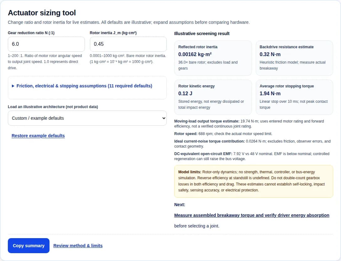
Change ratio and rotor inertia for live estimates. All defaults are illustrative; expand assumptions before comparing hardware.
Engineering review: . Product data checked on this date; revision and test conditions still govern.
Primary sourcesKey decisions before choosing a backdrivable actuator
Keep friction and inertia separate
A 6:1 ratio gives a 36× rotor inertia multiplier. Breakaway torque still needs an assembly test; a single transparency score hides this distinction.
[WENSING2017]Do not infer self-locking from ratio
An 80:1 strain-wave component set can have finite backdriving torque. A gravity load needs a separate verified holding strategy.
[HARMONIC]Require a regeneration energy path
Open-circuit EMF compared with nominal voltage cannot establish electrical protection. Verify drive limits, charge acceptance, and braking duty.
[BRAKING]Measure bandwidth rather than ranking gearbox names
The 2016 ANYmal compliant joint tests report over 70 Hz torque bandwidth. Springs and high ratios alone do not set a universal limit.
[HUTTER2016]1. What the tool calculates — and what needs measurement
A backdrivable actuator lets output-side torque move the motor through the transmission in a specified electrical state. This page covers the complete motor, transmission, driver, and sensing package. For measured torque screening and basic reducer terminology, see the backdrivability guide.
τ_resistance,estimate = Nτ_drag,motor / η_rev + τ_drag,gearbox
τ_output,estimate = Nτ_motor,ratedη_fwd
Rotor inertia is referred through an ideal rigid ratio. The resistance expression is a heuristic: efficiency is undefined at standstill, and gearbox drag must exclude losses already included in η_rev. Forward efficiency is entered independently. The output-torque expression applies to an assumed moving operating point; it does not model a joint thermal rating or stall losses. All fields are required, with example defaults and stated input ranges.
Record measured breakaway torque and running drag at multiple speeds, temperatures, loads, and drive states. Do not equate the input starting torque in a reducer catalog with output backdriving torque. [HARMONIC-CATALOG]
2. Reflected inertia, stored energy & stopping assumptions
τ_rotor,average = J_ref · Δω_joint / Δt
1 kg·cm² = 10⁻⁴ kg·m²; 1 g·cm² = 10⁻⁷ kg·m²
The model describes stored rotor energy and average rotor inertial torque under a linear stop. It omits links, payload, gearing, elasticity, and external work. It cannot estimate peak tooth stress, contact force, or energy dissipated in an impact. [WENSING2017]
| Ratio N | N² multiplier | J_ref (kg·m²) | Rotor energy (J) |
|---|---|---|---|
| 1:1 | 1× | 0.000045 | 0.00324 |
| 6:1 | 36× | 0.00162 | 0.11664 |
| 16:1 | 256× | 0.01152 | 0.82944 |
| 100:1 | 10,000× | 0.45 | 32.4 |
3. Architecture tradeoffs & application fit
Use these qualitative engineering comparisons to shortlist candidates. Ratios below are examples, not class boundaries. No architecture alone guarantees impact tolerance, human contact safety, low drag, or a particular force bandwidth. [KATZ2018][HUTTER2016]
| Architecture | Example ratio | Potential benefit | Required verification | Candidate use |
|---|---|---|---|---|
| Direct drive | 1:1 | No gearbox losses; motor drag remains | Rotor inertia and continuous holding heat | Haptics or joints with a suitable motor envelope |
| QDD / low-ratio planetary | 6:1 example | Low ratio can reduce referred inertia | Winding heat, real drag, and driver energy path | Dynamic contact, subject to torque-speed duty |
| Multi-stage planetary | 16:1 example | More torque leverage in a compact motor | Stage losses, backlash, and bearing loads | Payload-driven joints with measured drag limits |
| Strain wave | 80:1 example | Compact reduction and low backlash | Backdrive torque, nonlinear stiffness, and fatigue | Precision positioning with system-level force control |
| Series elastic actuator | Ratio depends on design | Deflection sensing and mechanical compliance | Spring travel, resonance, control, and packaging | Contact tasks needing physical elasticity |
4. Motor geometry: torque, rotor inertia & heat
For a radial-flux motor with uniform tangential air-gap shear stress σ and active length L, T = 2πσr²L. This is a scaling relation under fixed loading assumptions, not proof of a fixed torque-density advantage. A larger radius can increase rotor inertia as well as torque. Compare the complete motor-reducer pair at the required duty. [SEOK2015]
| Motor geometry | Opportunity | Tradeoff | Selection evidence |
|---|---|---|---|
| Large-radius radial-flux motor | Torque scales with air-gap surface shear and moment arm | A larger radius can also raise rotor inertia | Check measured K_m, winding temperature, and package inertia |
| Compact inrunner | Can pair low rotor inertia with higher speed | Reduction needed for output torque raises N²J_m | Compare complete motor + reducer inertia and loss |
| Axial-flux motor | Short axial package may fit flat joints | Thermal path and structural deflection depend on design | Require thermal and torque-speed data, not topology claims |
5. Manufacturer evidence: known values & procurement gaps
Snapshot checked 2026-10-27. These are manufacturer claims for specific revisions, not independent tests or an apples-to-apples ranking. A reducer component set excludes the motor and driver present in an integrated module. Peak torque is not continuous torque and requires a duration and operating condition.
| Product & source | Ratio | Published torque | Backdrive / starting torque | Mass | Unknown or to confirm |
|---|---|---|---|---|---|
| CubeMars AK80-9 V3.0 KV100 [CUBEMARS] | 9:1 | 9 N·m rated / 22 N·m peak | 0.51 N·m (catalog back drive) | 490 g | Breakaway test conditions and thermal mounting; listed rotor inertia 1118.3238 g·cm² needs revision/reference confirmation. No derived inertia ranking. |
| Unitree GO-M8010-6 [UNITREE] | 6.33:1 | 23.7 N·m maximum; continuous rating N/A in cited page | N/A — not published on cited page | About 530 g | Rotor inertia, breakaway torque, and continuous thermal duty; do not substitute estimated values. |
| Harmonic Drive CSG-20-80-2A-GR component set [HARMONIC] | 80:1 | 44 N·m rated L10 / 96 N·m repeated peak | 4.6 N·m (output backdriving); input starting torque is a separate 4.5 N·cm | 0.28 kg (component set only) | Motor, driver, mounting bearings, and assembled system thermal/drag behavior are not included. |
The cited AK80-9 V3.0 page currently lists rotor inertia as 1118.3238 g·cm². Earlier material and other revisions use different values; request the supplied revision and reference plane before deriving reflected inertia. The GO-M8010-6 page does not provide a comparable breakaway or rotor-inertia test. Leave those inputs unknown until the supplier confirms them.
6. Current feedback estimates motor torque, not contact force
δτ_current,ideal = N K_t δI_q
The displayed noise contribution omits friction, current-loop bias, cogging, gravity, inertial torque, and filtering. A joint torque in N·m becomes contact force in N only through known contact geometry and a suitable Jacobian. Calibrate an external torque observer across angle, speed, load, and temperature before using its output for control. [WENSING2017][MAXON]
For observer design and control tradeoffs, continue with force control in robotics and impedance control.
7. Dual encoders: torsional deflection & uncertainty
τ_elastic,estimate = K_torsional Δθ (sign defined by calibration)
Synchronize and unwrap both encoder angles, remove zero offsets, and identify stiffness with known bidirectional loads. Encoder quantization, offsets, backlash, nonlinear stiffness, and hysteresis can dominate a small deflection signal. Use an error budget and reference torque calibration; two encoders do not automatically make a torque sensor. The Harmonic Drive product data, for example, lists multiple stiffness regimes. [HARMONIC]
8. Regeneration: separate EMF comparison from energy absorption
Use a separately measured K_e with a documented voltage and speed convention. Here it means DC-equivalent rectified open-circuit voltage per motor mechanical rad/s. K_t and K_e are numerically interchangeable only with compatible definitions. EMF = K_eN|ω_joint| is a nominal comparison, not a bus-voltage prediction.
An active inverter can regenerate below the nominal bus voltage. In an unpowered but connected drive, rectifier paths depend on the bridge and electrical state. Establish the actual energy path, voltage/current ratings, and supply charge acceptance; a TVS for short transients is not a substitute for a rated repetitive braking sink.
| Quantity | Formula / bound | Boundary or required action |
|---|---|---|
| Rotor stored energy | E_rotor = ½N²J_mω² | One contribution to energy; add links, payload, gravity, and continuing external work. |
| Capacitor-only energy balance | C ≥ 2E_bus / (V_max² − V_initial²) | Requires V_max > V_initial and a defined net E_bus. Include simultaneous axes, voltage tolerance, ESR, and ripple; not a complete protection design. |
| Chopper current lower bound | R ≥ V_bus,max / I_switch,max | Also obey the drive minimum resistance and component tolerances. An undersized resistance can overcurrent the switch. |
| Braking power upper bound | R ≤ V_on² / P_required | Check available duty, peak/pulse energy, average heat, wiring, and thermal cutout. If bounds conflict, change the drive or energy sink. |
The current limit sets a lower resistance bound; power absorption sets an upper bound. Evaluate current at the highest allowed bus voltage, and include pulse and average thermal limits. The general selection logic is documented by Schneider Electric; its industrial drive voltage examples are not robot-driver recommendations. [BRAKING]
9. Thermal duty & the motor constant
This compact expression requires matched torque, current, and resistance conventions, including phase factors for three-phase motors. K_m has units N·m/√W. It is not torque per watt. Account for speed-dependent iron loss, inverter loss, ambient temperature, mounting conduction, and torque-speed-time duty. The calculator uses your entered motor rating; it does not simulate cooling or prescribe a universal derating percentage. [SEOK2015][MAXON]
10. Turn the result into an actuator acceptance plan
Before requesting a quote, specify torque-speed duty, load inertia, drag limits, thermal mounting, electrical states, bearing loads, envelope, and regeneration behavior. Set acceptance limits from your application and the supplier manual. The following plan is an engineering proposal, not a published industry threshold.
| Gate | Test evidence | Acceptance basis | Risk if omitted |
|---|---|---|---|
| Backdrive resistance | Measure both directions, cold/warm, with documented drive/brake states | Application-defined maximum breakaway and running drag; include uncertainty | Unexpected resistance or unstable torque estimation |
| Regeneration | Instrument bus voltage/current during representative deceleration and backdriving | Supplier voltage/current limits, clamp thresholds, pulse energy, and supply charge acceptance | Trips, component overload, or loss of torque control |
| Thermal duty | Reproduce torque-speed-time cycle and actual mounting/cooling to equilibrium | Vendor winding, magnet, bearing, and driver limits with agreed margin | Holding-torque derating or reduced component life |
| Sensing and stiffness | Apply known bidirectional loads; compare current and encoder estimates with reference torque | Application error budget over angle, load, temperature, and bandwidth | Observer bias, hysteresis, or position/torque loop instability |
| Mechanical load survival | Use a guarded, instrumented fixture and an agreed joint load spectrum | Supplier bearing, gear, fatigue, and alignment limits; inspect after test | Unrepresentative drop tests or undetected structural damage |
11. Bench states & a reproducible backdrive protocol
- Restrain gravity loads and use a guarded fixture with a calibrated output torque transducer and encoder.
- Document the exact electrical state: mechanically disconnected motor, open phases, connected unpowered driver, or active torque control. Follow the driver manual; do not improvise phase shorting.
- Ramp output torque slowly in both directions. Record onset of motion, running drag versus speed, lubricant and winding temperature, preload, and mounting conditions.
- Repeat under the intended load and thermal envelope. Report uncertainty and compare against the agreed application limit.
The catalog backdriving values use stated reference conditions and cannot be assumed to hold for every assembled joint. [HARMONIC-CATALOG]
12. Worked scenarios & published system evidence
The three calculations below are illustrative scenarios, not customer results or measured product performance. Their assumptions and arithmetic can be reproduced independently.
Illustrative ratio tradeoff
Assumptions: Same rotor J_m = 0.45 kg·cm² = 4.5×10⁻⁵ kg·m²; joint speed 12 rad/s. Ignore transmission and load inertia.
Method: Compare N = 6 and N = 16 using J_ref = N²J_m and E = ½J_refω².
Result & limit: 6:1 gives 0.00162 kg·m² and 0.11664 J; 16:1 gives 0.01152 kg·m² and 0.82944 J. At equal motor torque the higher ratio offers more leverage, but these values do not predict impact strength.
Illustrative stopping-time sensitivity
Assumptions: Use the 6:1 example above at 12 rad/s; assume linear deceleration with no external load contribution.
Method: Calculate average rotor inertial torque J_refω/Δt for 10 ms and 5 ms.
Result & limit: The estimates are 1.944 N·m and 3.888 N·m. The doubled average is a model sensitivity result, not a peak force or tooth-stress test.
Illustrative capacitor-only energy budget
Assumptions: Assume net energy delivered to the bus is 1 J, initial bus 48 V, chosen maximum 60 V, no other storage or sink.
Method: Use C ≥ 2×1 / (60²−48²); the energy assumption is independent of mechanical reverse efficiency.
Result & limit: The ideal minimum is 0.001543 F, approximately 1543 µF. This does not select a real capacitor bank: tolerances, ESR, repetition, driver limits, and supply state require verification.
Published low-ratio design evidence: Katz’s 2018 MIT thesis documents modular actuator hardware and controls for a small quadruped, with additional teleoperation and biped applications. It supports using an integrated motor, transmission, and control design process; it does not validate the tool presets as commercial product specifications. [KATZ2018]
Evidence against a universal SEA bandwidth ceiling: Hutter et al. report torque-control bandwidth above 70 Hz for the 2016 ANYmal compliant joint modules. That result belongs to the tested assembly and controller, not every series elastic actuator. [HUTTER2016]
13. Misuse, cost & scenario mismatch
| Risk | Why it matters | Mitigation or alternative |
|---|---|---|
| Misuse: inferred safety | A small rotor energy estimate excludes link and payload inertia | Measure system contact/stopping behavior; add passive compliance or lower speeds where needed |
| Cost: incomplete module comparison | Reducer-only prices omit motor, driver, bearings, calibration, and cooling | Compare installed system cost and service effort on the same duty cycle |
| Scenario mismatch: long holding duty | A low ratio can increase required motor current and heat | Verify equilibrium duty; evaluate a larger motor, alternative ratio, or a separate holding brake |
| Power loss: assumed holding | A backdrivable joint can release a gravity load when torque is removed | Provide a load restraint or rated holding brake; validate the power-loss state |
These are application review prompts. Backdrivability is not a substitute for a system risk assessment, load restraint, or validated contact behavior. [ISOTS15066]
14. Frequently asked actuator selection questions
Physics & Model Limits
Evidence and further reading: [WENSING2017][HARMONIC-CATALOG]
What defines a backdrivable actuator?
External output torque can drive the transmission and motor backward in a specified electrical state. Breakaway torque, running drag, speed, load, and temperature determine whether that motion is useful for the application.
Why does rotor inertia scale with N²?
The rotor spins at N times joint speed. Substituting ω_motor = Nω_joint into E = ½J_motorω_motor² gives the output-referred term N²J_motor. This excludes gears, links, payload, and compliance.
Is a transparency percentage a standard actuator rating?
No universal percentage is used here. Dividing breakaway torque by rated torque can conceal a large absolute resistance and ignores dynamic inertia. Compare measured drag and reflected inertia separately against application limits.
Can reverse efficiency predict static breakaway torque?
Only as a rough loss assumption. Efficiency is a power ratio and is undefined at zero speed. Preload, lubricant, seals, temperature, and electrical state require a separate assembled breakaway test.
Does high reduction mean that a joint is self-locking?
No. High ratios increase the rotor inertia multiplier but do not prove self-locking. Harmonic Drive publishes finite backdriving torque values and advises using a fail-safe brake for holding loads.
Choosing a Joint Architecture
Evidence and further reading: [KATZ2018][HUTTER2016]
When should I shortlist QDD?
Shortlist it when low output drag and low reflected inertia support dynamic contact tasks. Check motor thermal duty, peak torque duration, gear strength, bearing loads, and driver regeneration before choosing a ratio.
Does series elasticity always limit control bandwidth to 20 Hz?
No. Bandwidth depends on actuator mechanics, load, sensing, controller, and measurement method. The 2016 ANYmal paper reports torque control bandwidth above 70 Hz for its compliant joint modules.
Why consider direct drive?
It removes gearbox friction and backlash. Rotor inertia, bearing friction, cogging, mounting stiffness, and winding heat remain. Evaluate motor size and thermal duty at the required output torque.
Are all planetary reducers easy to backdrive?
No. Stage count, preload, seals, lubricant, assembly tolerances, and load affect resistance. Request measured drag curves for the assembled joint rather than inferring backdrivability from the architecture name.
How do I compare actuator cost without a misleading unit-price ranking?
Compare complete installed systems: motor, reducer, bearings, encoders, driver, thermal hardware, cabling, integration, calibration, and service. Public evidence here does not support a like-for-like price ranking.
Sensing & Electrical Behavior
Evidence and further reading: [WENSING2017][MAXON][BRAKING]
Can motor current measure external joint torque?
Current estimates electromagnetic torque through a calibrated K_t. External torque estimation must also account for inertia, gravity, friction, transmission losses, and controller dynamics. This is not a direct contact force measurement.
Is N·K_t·current noise the minimum detectable contact torque?
No. It is only an ideal motor-current noise contribution referred to the output. Actual detection also depends on friction, torque ripple, calibration, filtering, observer bias, and contact geometry.
Can K_t be copied directly into the K_e field?
Only after confirming compatible definitions. Phase versus line-to-line, RMS versus peak, and mechanical versus electrical speed conventions can introduce conversion factors. The tool requires a separate DC-equivalent measured K_e.
Is a back-EMF estimate below nominal bus voltage reassuring?
It does not establish protection. An active inverter can regenerate energy even when open-circuit EMF is below bus voltage. Supply charge acceptance, bus capacitance, clamp behavior, and actual overvoltage limits still need verification.
Can dual encoders replace a torque sensor?
They can support a calibrated elastic-deflection observer. Angle synchronization, zero offsets, stiffness variation, backlash, and hysteresis limit accuracy. Validate against a reference transducer before relying on the observer.
Verification & Procurement
Evidence and further reading: [HARMONIC-CATALOG][BRAKING][ISOTS15066]
How should breakaway torque be measured?
Restrain the load and use a calibrated output torque transducer. Record the electrical state, temperature, direction, speed ramp, and mounting. Measure both start-up resistance and running drag across the required range.
What does the assumed stopping time change?
The rotor-only average inertial torque is J_ref·Δω/Δt. Halving the assumed time doubles that value. Actual peak joint and contact loads require a load model or instrumented test; the tool does not predict them.
How should a brake resistor be selected?
Respect the actual drive minimum resistance and peak current limits, then ensure resistance is low enough to absorb the required power. Check pulse energy, repetition rate, resistor tolerance, thermal protection, and fault behavior.
Does low backdrive torque establish collaborative robot safety?
No. Contact geometry, speed, payload, trapping, stopping behavior, and system risk assessment remain relevant. This calculator does not test conformity with ISO/TS 15066 or any other safety standard.
What should I send with an actuator RFQ?
Send torque-speed and duty cycles, load inertia, mounting and cooling conditions, acceptable measured drag, supply and regeneration limits, bearing loads, envelope, electrical states, and acceptance test requirements.
15. Primary sources, scope & review date
Responsible publisher: Humanoid Joint. First recorded: (source history; public publication date unverified). Reviewed . Next evidence review due . This is an engineering screening guide with source-backed facts, explicitly illustrative calculations, and proposed procurement checks. Unknown product values remain unknown. It does not certify hardware, predict injury, or validate a control system. Recheck manufacturer revisions and current standards before design approval.
[WENSING2017] Proprioceptive Actuator Design in the MIT Cheetah: Impact Mitigation and High-Bandwidth Physical Interaction for Dynamic Legged Robots
P. M. Wensing, A. Wang, S. Seok, D. Otten, J. Lang, and S. Kim · IEEE Transactions on Robotics; DOI 10.1109/TRO.2016.2640183 · 2017 · Checked 2026-10-27
Research basis for low reflected inertia and current-based torque estimation; no universal collision or sensing threshold is implied.
[SEOK2015] Design Principles for Energy-Efficient Legged Locomotion and Implementation on the MIT Cheetah Robot
S. Seok et al. · IEEE/ASME Transactions on Mechatronics 20(3), 1117–1129 · 2015 · Checked 2026-10-27
Motor geometry, transmission loss, regenerative electronics, and thermal loss must be considered together.
[KATZ2018] A Low Cost Modular Actuator for Dynamic Robots
Benjamin G. Katz; advisor Sangbae Kim · MIT S.M. thesis, Mechanical Engineering · 2018 · Checked 2026-10-27
Open research reference for actuator hardware and control integration; not a datasheet for commercial AK-series motors.
[HUTTER2016] ANYmal – A Highly Mobile and Dynamic Quadrupedal Robot
M. Hutter et al. · IROS 2016, 38–44; ETH accepted manuscript · 2016 · Checked 2026-10-27
Compliant joint modules achieved over 70 Hz torque control bandwidth in the reported tests; series elasticity does not imply a universal low bandwidth ceiling.
[CUBEMARS] AK80-9 V3.0 KV100 – Official Specifications
CubeMars · Manufacturer product page, Specification table · undated · Checked 2026-10-27
Revision-specific 9:1 module specifications. Confirm thermal rating conditions and the inertia reference before using catalog data in a design.
[UNITREE] GO-M8010-6 – Bionic Robot Joint Motor
Unitree Robotics · Manufacturer product parameters · undated · Checked 2026-10-27
Publishes ratio, maximum torque, speed, and mass. Does not establish breakaway torque or rotor inertia for this screening model.
[HARMONIC] CSG-20-80-2A-GR – Gear Performance Data
Harmonic Drive LLC · Manufacturer component-set specifications · undated · Checked 2026-10-27
80:1 component set with finite specified backdriving torque; not a complete motor/driver module or a holding brake.
[HARMONIC-CATALOG] CSF / CSG Catalog – Starting Torque and Backdriving Torque
Harmonic Drive LLC · Engineering catalog, printed p. 48 (PDF p. 48), tables 36–39 · undated · Checked 2026-10-27
Separates input starting torque from output backdriving torque; specifies 20°C reference conditions and advises a fail-safe brake for holding.
[BRAKING] Criteria for Braking Resistor Selection
Schneider Electric · Technical FAQ FA376712; updated 2026-04-22 · 2026 · Checked 2026-10-27
Minimum resistance protects the switching transistor; maximum resistance limits available braking power. Actual drive limits and duty ratings govern selection.
[MAXON] Formulae Handbook – Motor Sizing and Operating Cycles
maxon · Motor engineering handbook · undated · Checked 2026-10-27
Motor current, torque constants, and operating-cycle conventions must be consistent when estimating heating and torque.
[ISOTS15066] ISO/TS 15066:2016 – Robots and Robotic Devices: Collaborative Robots
International Organization for Standardization · Technical specification; status checked 2026-10-27 · 2016 · Checked 2026-10-27
Applies to collaborative industrial robot systems, not non-industrial robots; its principles may inform other robotics. Mechanical backdrivability alone does not establish safety or conformity.
Build a measurable actuator specification
Bring your torque-speed duty cycle, drag limits, supply and regeneration requirements, and mounting envelope. Use the acceptance plan above to turn an initial shortlist into testable joint requirements.