
Joint Torque Sensors vs. Proprioceptive Current Sensing in Humanoid Actuators: A 2026 Engineering and Procurement Guide
Compare joint torque sensors vs current sensing for humanoid actuators: friction, bandwidth, calibration and cost. Use the RFQ checklist to brief suppliers.
Joint torque sensors vs proprioceptive current sensing is a choice about where torque is measured and how much uncertainty your application can tolerate. An output-side sensor measures transmitted joint torque; motor current estimates electromagnetic torque before transmission losses. Neither signal alone gives a complete measurement of external contact force.
For actuator architects and procurement teams, the practical question is: Which joints need direct torque feedback, and where can a validated current or dual-encoder observer meet the task requirements? Fine assembly, contact-rich manipulation, and dynamic locomotion place different demands on this decision.
Reviewed: November 5, 2026. Scope: global engineering and procurement guidance for electrically driven humanoid robot joints. This is a literature-informed selection framework, not a hardware benchmark or certification assessment. Numerical examples below are explicit assumptions; actual performance, cost, and compliance require supplier evidence and application testing.
Preparing a sourcing brief? Start with the Humanoid Joint RFQ Template (CSV), then add the sensing requirements in Section 7.
1. Executive Comparison & Physical Bottlenecks
Every robotic actuator acts as an energy transducer, but torque can be measured at different points along the drivetrain. For a simplified rotary actuator, use this output-side balance:
τ_drive,out ≈ N × Kt × iq − τ_loss,out − (N² × Jm) × αout
Here, N is the reduction ratio, Kt is the motor torque constant, iq is torque-producing current, Jm is rotor inertia, and αout is output acceleration. Loss torque represents the drivetrain losses referred to the output. Do not also subtract a full efficiency loss if the same loss is already included in that term. Match the supplier's current convention to Kt; peak, RMS, and controller-specific dq conventions are not interchangeable.
This balance estimates delivered drive torque. Separating contact torque still requires the link's gravity, inertia, and other loads. Off-axis bearing loads need their own mechanical model; they are not interchangeable with torque about the joint axis.
The Friction Wall in High-Reduction Drivetrains
High reduction can make small output disturbances difficult to distinguish from friction, preload, and transmission hysteresis. There is no universal ratio or deadband at which current sensing fails. Ask for bidirectional torque-current curves at the intended speed, load, and temperature, including zero-speed breakaway and direction reversal.
A room-temperature compensation map may become inaccurate after warm-up. The useful procurement question is whether the complete observer retains the required error envelope throughout the duty cycle, rather than whether a supplier quotes one nominal efficiency figure.
Reflected Inertia and Shock Attenuation
Reflected rotor inertia scales with the square of the reduction ratio: Jref = N² × Jm. As a reproducible example, a ratio of 100 and rotor inertia of 0.00015 kg·m² give 1.5 kg·m² at the output. This is a kinematic calculation, not a measured impact result.
The MIT Cheetah proprioceptive actuator study explains why low-inertia, backdrivable transmission design matters for dynamic interaction. Its robot-specific results do not establish universal humanoid thresholds. Compare mechanical impact response with electrical current-loop response separately.
Conceptual topology diagram: signal locations and limitations, not product ratings.
2. Electromechanical Comparison: Three Sensing Paradigms
Paradigm A: Dedicated Strain-Gauge Joint Torque Sensing
A precision flexure in the torque load path carries strain gauges, commonly arranged as a Wheatstone bridge. Its location matters: an output-side element can measure transmitted torque without inferring gearbox losses from motor current. A housing-reaction sensor needs interpretation according to its actual mounting and load path.
- Friction independence: Output sensing reduces reliance on a gearbox friction model. It still measures gravity and acceleration loads as well as contact, and remains subject to its own drift, mounting effects, and cross-talk.
- Sensitivity and linearity: Compare absolute error in Nm, repeatability, hysteresis, and usable resolution across the operating range. ADC bit count alone cannot establish torque accuracy.
- Bandwidth and stiffness: A flexure in series adds compliance. In a simplified fixed-motor, single-load model,
fres = sqrt(kτ / Jlink) / (2π). Assuming 12,000 Nm/rad and 0.08 kg·m² gives about 61.6 Hz. A coupled motor-gearbox-link assembly has additional modes; controller gains require its measured frequency response.
The DLR lightweight robot paper is background on lightweight robot design and control in human environments. It is not evidence for a particular supplier's accuracy or overload claims.
Paradigm B: Proprioceptive Motor Current Sensing
This approach uses the motor drive's current measurement and a motor/transmission model. When current sensing already exists for motor control, the additional sensing hardware can be small. Engineering effort remains: current offsets, torque-constant variation, friction identification, filtering, and thermal validation all affect cost.
Low-ratio, backdrivable designs are attractive candidates because losses and reflected inertia can be reduced. A fast FOC update rate does not establish equally fast output-torque regulation or collision detection. Request measured signal latency and closed-loop response at the link, with the specified load attached.
For high-ratio joints, reject blanket claims that current sensing is always adequate or always impossible. Judge its residual error against the smallest relevant disturbance, especially during holding, slow reversal, and warm-up.
Paradigm C: Dual-Encoder Deflection-Based Virtual Torque Sensing
With a motor encoder and output encoder, a simple motor-leading sign convention gives Δθ = θmotor / N − θlink. A locally linear approximation is τestimated = kgear × Δθ. Real transmissions may require direction-dependent, nonlinear stiffness and hysteresis maps.
This architecture reuses gearbox compliance; encoders do not absorb impact energy. Synchronization, mounting runout, encoder accuracy, and thermal behavior affect the difference signal. If output-angle uncertainty were 0.001 rad and local stiffness 10,000 Nm/rad, its torque-equivalent uncertainty would already be 10 Nm before other errors. That illustrative calculation explains why nominal encoder bit depth is insufficient for selection.
3. Comprehensive Engineering and Procurement Matrix
Use these nine comparison points to structure supplier questions. The entries describe mechanisms and evidence requirements, not universal performance specifications.
| Performance Metric | Dedicated Strain-Gauge Torque Sensor | Proprioceptive Motor Current Sensing | Dual-Encoder Deflection Virtual Torque |
|---|---|---|---|
| Measurement location | Actual sensor load path; verify output or reaction mounting | Motor drive current measurement | Relative motor/output angle |
| Low-torque capability | Verify error, noise, and hysteresis in Nm | Limited by current/model uncertainty and drivetrain losses | Limited by angle uncertainty and stiffness model |
| Drivetrain friction | Output sensing reduces dependence on loss estimates | Requires loss identification or observer compensation | Gear hysteresis affects torque-deflection mapping |
| Thermal behavior | Flexure, bridge, electronics, and mounting can drift | Motor constant and friction model can drift | Encoder geometry and transmission stiffness can drift |
| Dynamic bandwidth | Separate sample rate, filter delay, and mechanical response | Separate FOC update rate from output-torque response | Separate acquisition rate from filtered observer bandwidth |
| Torsional stiffness | Series flexure can reduce assembled stiffness | No additional sensing flexure required | Uses existing drivetrain compliance |
| Shock and overload | Verify flexure protection and full assembly load limits | Gearbox, bearings, rotor, and housing still need qualification | Encoders add no mechanical shock protection |
| Incremental cost | Quote sensor, electronics, calibration, and integration | Include modeling, software, and qualification effort | Quote second encoder, alignment, synchronization, and calibration |
| Factory calibration | Bidirectional torque, temperature, cross-axis loading | Current offsets, motor constant, loss map | Encoder alignment, stiffness, hysteresis, temperature |
For available packaging families, compare the Product Catalog against the RFQ rather than assuming every configuration includes torque sensing.
4. Mechanical Design Realities: Packaging, Overload, and Cross-Talk
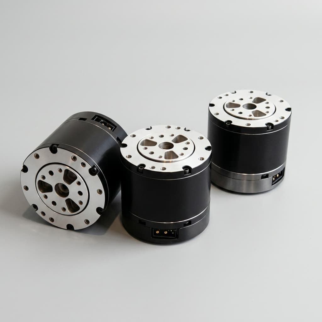
Motor packaging reference. This image does not show an installed torque sensor or verify a hollow-shaft assembly's cable clearance.
The Overload Hard-Stop Dilemma
A strain-gauge sensor relies on elastic deformation. A collision can exceed its calibrated range without immediately causing failure; permissible overload, ultimate strength, fatigue life, and measurement range are separate specifications.
Mechanical stops can bypass a flexure after engagement, but clearance, tolerance stack, contact stiffness, and the housing load path determine what happens next. A static overload percentage does not establish survival under a fall with combined bending, axial force, and repeated impacts. Request the applied pulse, fixture, load direction, and post-test zero-shift criterion.
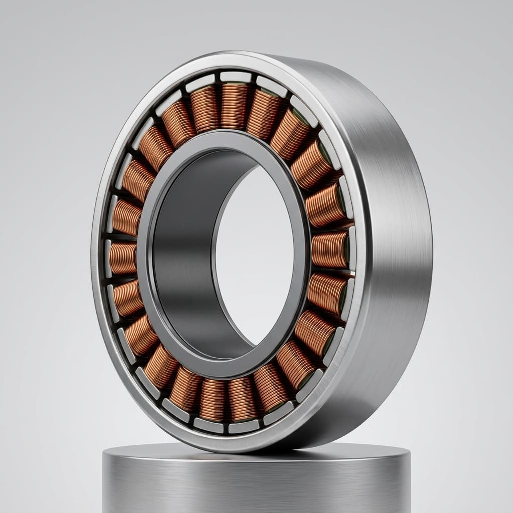
Conceptual flexure schematic; dimensions, materials, and protective features must be confirmed on the selected design.
Cross-Axis Moment Rejection and Thermal Zero Drift
Real joints experience bending and axial/radial loading alongside torsion. Symmetric bridges can reduce unwanted sensitivity, but mounting preload and manufacturing variation leave residual errors. Ask for a cross-axis error matrix with the applied load, error units, and rated combined-load envelope specified.
Test zero and span over the intended temperature range. Housing temperature may lag the sensor or winding temperature, so a single case thermistor is not automatically an adequate compensation input. The calibration report should identify warm-up time, gradients, load points, and whether limits apply before or after compensation.
5. Humanoid Whole-Body Sourcing Matrix: DOF Allocation
A hybrid allocation can be a useful starting point. The following zones are a screening framework, not a survey of leading OEM practice or a universal body plan. Actual DOF counts, coupled mechanisms, and transmission choices vary.
| Humanoid Kinematic Zone | Example DOF Layout | Candidate Architecture | Evidence Needed Before Selection |
|---|---|---|---|
| Wrist | Up to 3 per hand | Direct torque sensing for small-contact tasks | Low-torque error under cable drag, payload, and bending |
| Elbow | 1 per arm | Direct sensor or validated observer | Holding-load accuracy and slow reversal behavior |
| Shoulder | Up to 3 per arm | Direct sensor or dual-encoder observer | Extended-arm stiffness, gravity compensation, cross-axis error |
| Waist / torso | 2–3 | Direct sensor or observer | Coupled upper-body dynamics and mounting load path |
| Hip yaw / roll | 2 per leg | Current observer, dual encoder, or direct sensor | Loaded backdrivability and lateral balance response |
| Hip pitch | 1 per leg | Current or deflection observer; direct sensing where justified | Swing/stance transitions and impact qualification |
| Knee | 1 per leg | Match sensing to rotary or linear transmission | Screw friction or gearbox losses, peak duty, fatigue |
| Ankle | Up to 2 per foot | Joint sensing and/or foot wrench sensing | Ground-contact estimation, shock survival, redundant coverage |
Foot force/torque sensing can complement joint feedback but measures a different quantity and needs its own overload qualification. Neither joint location nor transmission label establishes reliability.
6. Functional Safety and Standards Scope
The ISO 13482:2014 catalogue entry concerns personal care robots and excludes industrial robots from its scope. Determine the applicable requirements from intended use and deployment jurisdiction. An industrial humanoid application cannot be assigned a personal-care compliance route simply because the robot resembles a person.
Treat references to collaborative robot contact limits as application-specific engineering inputs. This guide does not prescribe body-region force limits or establish which standards edition applies to a deployment.
A torque sensor plus dual encoders does not automatically achieve a performance level, safety integrity level, or certification. Such claims require a defined safety function, suitable architecture, diagnostics, failure analysis, and validation. Safe Torque Off removes torque-producing drive power; it does not by itself stop a falling link or hold a suspended load.
Procurement should request the safety manual, certified scope where claimed, fault reaction, stopping-time evidence, and responsibility split between actuator supplier and robot integrator. Evaluate contact detection and stopping on the assembled mechanism, including gravity and stored energy. Sensor accuracy is one input to that assessment.
7. Engineering & Procurement RFQ Specification Checklist
Use this eight-point checklist to make quotes comparable. Set limits from the task and risk assessment; the article does not impose a universal torque, temperature, or interface rating.
- 1. Rated torque and load envelope: State continuous and peak duty, speed, duration, combined loads, overload pulse, and fatigue target. Distinguish actuator output rating from sensor measurement range.
- 2. Stiffness and dynamic response: Request assembled stiffness, frequency response under payload, filter delay, and demonstrated closed-loop response. Agree a stability margin with the controls team.
- 3. Measurement error: Specify allowable error in Nm as well as percent of full scale, bidirectional hysteresis, repeatability, and cross-axis loading conditions.
- 4. Thermal validation: Define ambient and operating temperatures, warm-up, duty cycle, zero/span drift, and compensation inputs. Include cold-start and warmed-up reversal tests.
- 5. Electronics and timing: Specify usable resolution, noise, output rate, end-to-end latency, timestamp synchronization, interface, packet-loss behavior, and inverter EMC test conditions.
- 6. Mechanical integration: Confirm usable bore clearance, cable bend radius, mounting preload, connector access, bearing loads, and controlled drawing revision.
- 7. Acceptance testing: Use a calibrated output torque reference. Test multiple loads and both directions at several temperatures; log current, both encoder angles where fitted, torque signal, and timestamps. Agree pass/fail limits before the purchase order.
- 8. Deliverables and commercial scope: Request serialized calibration data, firmware/version identifiers, compensation ownership, recalibration process, replacement interchangeability, tooling/NRE charges, and prototype versus production pricing.
The RFQ CSV provides a general project brief. Attach this sensing checklist separately; the download is not a sensor acceptance specification.
8. Sourcing Recommendations and Implementation Next Steps
- For manipulation-focused platforms: Start from the smallest relevant contact torque, then compare the complete measurement error against it. Output-side sensing is a strong candidate where loss-model uncertainty consumes that budget. Include gravity and tool loads when setting range; an oversized sensor can sacrifice useful low-torque resolution.
- For dynamic locomotion: Compare backdrivability, reflected inertia, impact load paths, and thermal duty before selecting the feedback architecture. Low-ratio current control is a candidate, not an exemption from gearbox, bearing, sensor, or fall testing.
- For cost-constrained production: Compare total installed and lifecycle cost. If dual encoders already exist, an observer may reduce incremental hardware; calibration, firmware maintenance, and unit-to-unit variation still need a budget.
Illustrative budgeting method: Assuming USD 120–250 incremental installed cost per directly sensed axis, 32 axes imply USD 3,840–8,000; eight selected axes imply USD 960–2,000. These assumed inputs are not quotations or market benchmarks. Obtain separate figures for electronics, calibration, yield loss, NRE, qualification, and service before comparing architectures.
Run a candidate joint against a calibrated output reference through holding, slow bidirectional motion, acceleration, and thermal soak. Record maximum and RMS residual error, latency, false detections, and missed disturbances against the agreed acceptance limits. Repeat the agreed production sample plan; a single tuned prototype cannot establish fleet-wide observer performance.
9. Frequently Asked Questions (FAQ)
Can motor phase current alone establish safe contact detection across a 100:1 harmonic drive?
No sensing architecture alone establishes safety compliance. At high reduction, friction and hysteresis can mask small output disturbances. Validate detection thresholds, stopping behavior, diagnostics, and contact forces on the assembled robot under the applicable safety requirements.
Why can integrated joint torque sensors lower structural bandwidth?
A sensor flexure adds compliance when placed in series with the output load path. The change depends on sensor stiffness, gearbox stiffness, mounting, and attached inertia. Measure the assembled frequency response; sensor sample rate is not closed-loop mechanical bandwidth.
How should joint torque sensors be qualified for falls and shock loads?
Request rated load, permissible overload, combined-load limits, fatigue data, and post-overload zero-shift results. Mechanical stops can bypass the flexure after engagement, but they do not certify that the complete actuator survives a fall.
How can buyers budget torque sensors for a 32-DOF humanoid?
As an illustrative budget, assume USD 120–250 of incremental installed cost per axis. Multiplying by 32 gives USD 3,840–8,000. These are planning assumptions, not supplier quotes or market benchmarks; calibration, electronics, tooling, and qualification scope must be confirmed.
Can dual-encoder deflection measurement replace dedicated torque sensors?
It can support load estimation when transmission stiffness, hysteresis, encoder errors, and timing are characterized. Suitability for fine manipulation depends on demonstrated error over temperature, load direction, and wear; adding encoders does not itself absorb impacts.
How does lubricant temperature affect proprioceptive current sensing?
Temperature changes lubricant behavior and drivetrain friction, shifting the relationship between current and delivered output torque. Measure cold-start and warmed-up behavior in both directions. No universal percentage applies across different greases, reducers, loads, and speeds.
10. References & Technical Sources
- Albu-Schäffer, A., Haddadin, S., Ott, C., Stemmer, A., Wimböck, T., & Hirzinger, G. (2007). The DLR lightweight robot: design and control concepts for robots in human environments. Industrial Robot: An International Journal. Publisher DOI: 10.1108/01439910710774386. Background on lightweight robot design and control; no supplier-specific ratings are inferred.
- Wensing, P. M., Wang, A., Seok, S., Otten, D., Lang, J., & Kim, S. (2017). Proprioceptive Actuator Design in the MIT Cheetah: Impact Mitigation and High-Bandwidth Physical Interaction for Dynamic Legged Robots. IEEE Transactions on Robotics, 33(3). Publisher DOI: 10.1109/TRO.2016.2640183. Background on backdrivability and proprioceptive actuator design; the experiments concern the MIT Cheetah, not humanoid vendor products.
- International Organization for Standardization. ISO 13482:2014 — Robots and robotic devices — Safety requirements for personal care robots. Official catalogue and scope. Used to distinguish personal-care from industrial application scope. Confirm the applicable edition and local adoption when planning deployment.
Sources and scope reviewed November 5, 2026. The equations, screening matrices, and assumed-cost arithmetic are explanatory analysis, not measured product results, customer case studies, or evidence of certification.
11. Engineering Consultation & RFQ Support
To discuss a candidate sensing architecture with Humanoid Joint, submit the joint location, transmission ratio, continuous/peak duty, smallest relevant contact torque, temperature range, and required measurement error through the Contact & RFQ Portal.
Use the Product Catalog to identify candidate packaging and the Humanoid Joint RFQ Template (CSV) to organize the project brief. Ask which sensor options, calibration reports, drawings, and qualification records are available for the exact configuration. Confirm specifications and lead times in the supplier response before placing an order.
Author

Categories
More Posts
Admittance Control vs. Impedance Control: A Hardware Sourcing and Architecture Guide
Compare admittance control vs. impedance control for humanoid joints: sensors, latency, actuator trade-offs, and RFQ checks. Contact Humanoid Joint today.
Harmonic vs. Cycloidal Drives in Humanoid Joints: Navigating Fatigue Failure
Compare harmonic and cycloidal drives for humanoid robot joints, fatigue risks, shock loads, and supplier checks before selecting durable actuator modules.

Active Short Circuit (ASC) vs. Mechanical Brakes in Humanoid Joints: Sourcing for ISO 13482
Compare ASC vs mechanical brakes for humanoid joints in 2026 sourcing. See SGF, BOM, weight, ISO 13482 limits, and RFQ checks before contacting engineering.