
Harmonic vs. Cycloidal Drives in Humanoid Joints: Navigating Fatigue Failure
Compare harmonic and cycloidal drives for humanoid robot joints, fatigue risks, shock loads, and supplier checks before selecting durable actuator modules.
For decades, the robotics industry has relied on a well-understood division of labor when it comes to speed reduction: Harmonic drives (strain wave gearing) dominated precision applications like robotic wrists and collaborative arms, while Cycloidal drives (including RV reducers) ruled the heavy-duty bases of six-axis industrial welders.
However, as we move through 2026, the rapid commercialization of bipedal humanoid robots is shattering these traditional paradigms. A 75kg humanoid walking dynamically across a concrete factory floor introduces biomechanical load profiles—specifically, continuous impact shock and cyclical fatigue—that simply do not exist in stationary robotic arms bolted to steel pedestals.
For procurement teams and hardware engineers tasked with scaling humanoid platforms, selecting the right reducer architecture for integrated joint modules is no longer just a question of torque-to-weight ratio. It is a critical decision regarding system longevity, maintenance cycles, and catastrophic fatigue failure.
This guide dissects the physical failure modes of harmonic and cycloidal drives under humanoid locomotion profiles, provides a clear procurement matrix for mixed-architecture systems, and details the engineering checklist required to validate your supplier's durability claims.
Scope and limits: Updated July 19, 2026, this article is for global humanoid robot joint teams selecting reducers for industrial prototypes and early production. Treat the recommendations as architecture-screening guidance, not a supplier lifetime guarantee; require your own load spectra, duty-cycle tests, lubrication plan, and supplier fatigue data before freezing a BOM.
If you are already preparing an RFQ, use the checklist below to request shock-load, backlash-growth, thermal, and integrated-module evidence before comparing reducer quotes.
The Locomotion Problem: Impact Shocks and Dynamic Loading
To understand why traditional reducer procurement fails for humanoids, you must understand the physics of a footstrike.
When a traditional industrial arm stops moving, it decelerates smoothly according to a pre-programmed trajectory spline. When a humanoid takes a step, its heel strikes the ground. This creates a high-frequency shockwave that travels upward through the ankle, knee, and hip joints. Even with advanced compliance control and series elastic actuators, a significant portion of this kinetic energy must be absorbed by the reducer's mechanical structure.
Furthermore, a humanoid recovering from a stumble or carrying an off-center payload exerts massive, unexpected reverse-torque spikes (backdriving forces) onto the joint.
Harmonic Drives: The Precision/Fatigue Trade-off
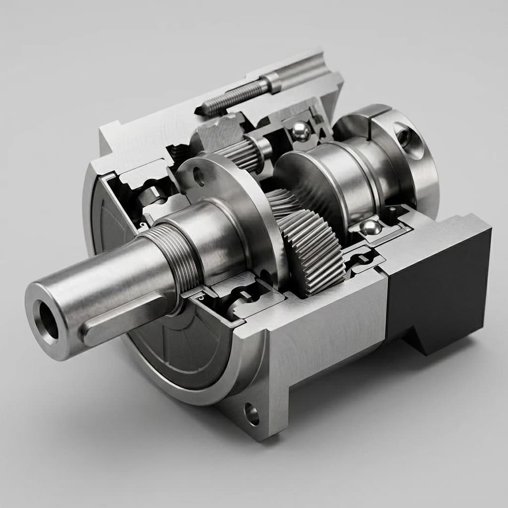
Harmonic drives are elegant devices consisting of three components: a Wave Generator (an elliptical cam), a Flexspline (a thin, flexible steel cup with external teeth), and a Circular Spline (a rigid ring with internal teeth).
The Mechanism of Fatigue: The beauty of the harmonic drive is its zero backlash, achieved by the continuous elastic deformation of the flexspline. The Wave Generator physically bends the steel cup into an ellipse, forcing its teeth to mesh with the Circular Spline at two opposite points.
However, this constant deformation is the drive's Achilles' heel in humanoid locomotion. Metal fatigue is cumulative. Every time the motor rotates, the flexspline bends. Under the continuous, jarring shock loads of bipedal walking, micro-fractures can initiate in the thin wall of the flexspline. If an unexpected torque spike (like a fall) exceeds the momentary yield strength of the fatigued metal, the flexspline will shear completely, resulting in a catastrophic joint failure where the limb instantly loses all torque and goes limp.
Cycloidal Drives (RV Reducers): The Robust Alternative
Cycloidal drives operate on a fundamentally different principle. An eccentric cam drives a cycloidal disc (or discs), forcing it to roll around a ring of fixed pins.
The Mechanism of Resilience: Unlike a harmonic drive, which relies on the bending of thin metal, a cycloidal drive relies on rolling contact pressure. Depending on tooth count, pin geometry, and preload, strain wave gears usually concentrate load in a smaller meshing zone, while cycloidal and RV-style reducers can spread overload across multiple lobes, rollers, or pins at once. Do not treat any generic percentage as universal; require the supplier's contact-ratio and overload-test evidence for the exact model.
When a massive shock load travels up a humanoid's leg, the cycloidal drive disperses that kinetic energy across a massive surface area of hardened steel. The primary failure mode is not a sudden, catastrophic shear of a single component, but rather a slow, gradual surface wear (spalling or pitting) on the cycloidal lobes or pins. The joint will become noisier and exhibit increased backlash over time, but it will rarely fail instantly.
Structural Failure Paths: Harmonic vs. Cycloidal under Shock Load
Figure 1: Mechanical stress distribution. Harmonic drives concentrate stress at the peak deformation points of the thin flexspline, whereas cycloidal drives distribute compression forces across multiple solid steel pins.
Procurement Strategy: The Mixed-Architecture Humanoid
Because of these inherent trade-offs, many humanoid development teams in 2026 are moving away from a single reducer technology for the entire robot. Instead, they evaluate a Mixed-Architecture Bill of Materials (BOM).
This strategy matches the physical characteristics of the reducer to the specific kinematic requirements of the joint location.
Procurement Matrix: By Joint Location
| Joint Location | Recommended Reducer | Primary Procurement Justification | Secondary Considerations | Expected Lifecycle Mode | Impact on Backdrivability |
|---|---|---|---|---|---|
| Ankles (Pitch/Roll) | Cycloidal | Bears the full dynamic shock of the footstrike. Highest impact loading in the system. | Must be sealed against environmental debris (IP67+). | Gradual wear, backlash increase over 5,000+ hours. | Excellent. Tolerates reverse driving well. |
| Knees (Pitch) | Cycloidal | Requires massive holding torque for crouching/lifting. Highly susceptible to reverse-torque spikes during stumbles. | Weight penalty of cycloidal drives is acceptable lower in the chassis. | Gradual wear. Requires regular lubricant monitoring. | Good. Enables impedance control algorithms. |
| Hips (Pitch/Roll/Yaw) | Mixed (Cycloidal preferred) | The nexus of upper body mass transfer. High torque, but slightly less acute shock than the ankle. | Size constraints often force engineers to evaluate high-capacity Harmonic drives if Cycloidals don't fit. | Varies by architecture. | Moderate. |
| Waist / Torso Rotation | Mixed (Cycloidal or high-capacity harmonic) | Handles upper-body inertia during turns, lifting, and balance recovery; less direct heel-strike shock than ankles or knees but high reversal cycles. | Packaging, cable pass-through, and brake placement often decide the architecture. | Backlash growth or flexspline fatigue, depending on reducer. | Moderate to Good if ratio and controller support torque transparency. |
| Shoulders / Elbows | Harmonic | Arms require high precision for manipulation tasks (grasping, tool usage) and minimal mass to keep the center of gravity low. | Low impact risk unless the robot falls directly on its arm. | Long life if kept within rated torque limits. | Poor to Moderate. High gear ratios reduce transparency. |
| Wrists / Neck | Harmonic | Extreme space constraints. Zero backlash required for precise end-effector positioning. | Load profiles are predictable and easily limited by software. | Very long life. Flexspline fatigue is rarely an issue here. | Poor, but largely irrelevant for these axes. |
Hidden Procurement Costs and Considerations
When evaluating supplier RFQs for integrated joint modules, purchasing teams must look beyond the sticker price and the basic rated torque specifications.
Use this section as a midpoint screen: a supplier that cannot explain weight impact, backlash growth, and reducer thermal behavior should remain in prototype-only status until the missing evidence is closed.
1. The Cost of Weight (The "Heavy Cycloidal" Penalty)
Cycloidal drives are fundamentally heavier than harmonic drives for a given diameter. If your engineering team decides to switch the hips and knees from Harmonic to Cycloidal to solve fatigue issues, the robot's overall mass will increase. This has cascading effects on your BOM: heavier legs require more powerful motors to swing them, which draw more current, which requires larger battery packs, which add more weight. You must model the Total Cost of Ownership (TCO) of this weight spiral against the cost of replacing sheared harmonic drives.
2. Backlash Degradation Over Time
Harmonic drives proudly advertise "zero backlash," and they generally maintain this until the moment they fail. Cycloidal drives begin with a small amount of backlash (e.g., 0.5 to 1 arcmin) and this backlash slowly increases as the pins wear down. For procurement, you must ask the supplier: "What is the guaranteed maximum backlash after 10,000 hours of continuous cyclical loading?" If your walking algorithms cannot tolerate 3 arcminutes of slop in the knee joint after a year of operation, the drive has effectively failed, even if it hasn't physically broken.
3. Lubrication and Thermal Limits
Cycloidal drives, due to their sliding/rolling friction across many pins, typically generate more heat than harmonic drives at high speeds. If your humanoid walks quickly, the thermal continuous torque limit of the joint might be dictated by the reducer's grease breaking down, rather than the motor's copper windings melting. Ensure your supplier's thermal wall specifications explicitly account for reducer heat generation under dynamic continuous duty cycles.
Supplier Verification Checklist
Do not accept generic industrial specifications for humanoid joints. Use this checklist during vendor qualification and prototype evaluation:
- Shock Load Rating Verification: Does the supplier provide a distinct "Momentary Peak Torque" rating specifically tested under high-frequency impact conditions, not just a static overload rating?
- Flexspline Material Data (Harmonic Only): Has the supplier provided the S-N (Stress-Number of Cycles) fatigue curve for their proprietary flexspline alloy?
- Acoustic Signature Tracking (Cycloidal Only): Does the supplier have data correlating an increase in acoustic noise (dB) to internal pin wear over time? (This is crucial for predictive maintenance algorithms).
- Grease Migration Testing: Under high-speed oscillatory motion (typical of humanoid walking), will the grease inside the reducer centrifuge away from the contact surfaces, causing dry running and accelerated wear?
- Integrated System Testing: Has the supplier tested the reducer while integrated with the motor, encoder, and fail-safe brake under a simulated bipedal walking load profile, or only on a sterile dynamometer?
Frequently Asked Questions (FAQ)
Q: Can we just use larger Harmonic drives in the legs to prevent fatigue failure? A: Upsizing the harmonic drive increases its torque capacity and thickens the flexspline, which improves fatigue life. However, a larger harmonic drive has significantly higher rotational inertia, which makes the joint less "transparent" and hinders the compliance algorithms necessary for smooth walking. It also rapidly increases the cost and diameter of the leg.
Q: Are there alternatives to these two technologies for humanoids? A: Yes. Some OEMs are utilizing Quasi-Direct Drive (QDD) architectures for the legs. QDD uses very low-ratio planetary gears (e.g., 6:1 or 10:1) paired with massive, high-torque gap motors. This provides incredible impact resistance and backdrivability, but forces the motors to draw immense continuous current to hold a static pose, severely limiting battery life. Planetary drives, generally, suffer from too much backlash for precision joints unless highly customized.
Q: Why does the robotics industry still rely on these older reducer designs? A: Developing a fundamentally new mechanical speed reduction paradigm is incredibly capital intensive. While there are emerging technologies (like Archimedes drives or advanced magnetic gearing), Harmonic and Cycloidal drives benefit from decades of established metallurgy, manufacturing scale, and predictable failure modes. The current innovation is focused on integrating them better, not necessarily replacing them.
Q: How does the reducer choice affect the safety certification of the robot? A: Catastrophic failure modes (like a flexspline shearing) must be accounted for in your ISO 13849-1 risk assessment. If a joint can fail instantly, your functional safety architecture must rely heavily on rapid detection via dual encoders and the immediate engagement of fail-safe brakes to prevent the robot from collapsing dangerously.
Securing the Future of Humanoid Locomotion
The transition from R&D prototypes to commercially viable, industrialized humanoid robots hinges on reliability. A humanoid that walks beautifully for 200 hours in a lab but snaps a knee joint after one month on a factory floor is a commercial failure.
By understanding the distinct fatigue profiles of Harmonic and Cycloidal drives, engineering and procurement teams can construct a highly optimized, mixed-architecture robot. Deploying robust cycloidal drives in the high-impact lower extremities while preserving the precision of harmonic drives in the upper body is the pragmatic path to achieving the 10,000+ hour lifecycle expected by industrial buyers.
At HumanoidJoint.com, we understand that durability is the ultimate specification. Our Integrated Humanoid Joint Modules are available with tailored reducer architectures—incorporating advanced material harmonic drives for manipulation and high-shock cycloidal configurations for locomotion.
If your engineering team is fighting joint fatigue or you are seeking to secure a reliable supply chain for scaling your humanoid platform, contact our applications engineering team at [email protected] or via WhatsApp at +86 18857971991 to review our durability testing data and custom integration capabilities.
Sources and Regulatory References
The mechanical comparisons and durability insights in this guide are synthesized from drive manufacturer references, supplier documentation, and safety standards. These sources support terminology and screening logic; they do not replace model-specific supplier test data for your robot's duty cycle.
| Source / Organization | Relevance | Status / URL |
|---|---|---|
| Harmonic Drive LLC | Strain wave gearing reference for wave generator, flexspline, circular spline, and zero-backlash positioning claims. | Verified reference harmonicdrive.net/technology |
| Laifual Drive (Zhejiang Laifual Drive Co., Ltd) | Manufacturer context for harmonic and RV/cycloidal reducer terminology in robotics applications. | Verified reference laifualdrive.com |
| Honpine Robotics | Supplier perspective on reducer selection, compact joint modules, and robot actuator packaging trade-offs. | Verified reference honpine.com |
| Cone Drive (Timken Company) | Industrial drive supplier context for high-load reducer selection and shock-duty screening. | Verified reference conedrive.com |
| ISO 13849-1:2023 | Safety-related control-system standard referenced when reducer failure modes affect risk assessment and safe stop design. | Verified reference iso.org/standard/69883.html |
For further insights into optimizing your actuator supply chain, explore our guide on In-House Assembly vs. Pre-Integrated Modules, or review our comprehensive Functional Safety Procurement Guide.
Author

Categories
More Posts
Active Short Circuit (ASC) vs. Mechanical Brakes in Humanoid Joints: Sourcing for ISO 13482
Compare ASC vs mechanical brakes for humanoid joints in 2026 sourcing. See SGF, BOM, weight, ISO 13482 limits, and RFQ checks before contacting engineering.
48V vs. 400V Humanoid Joint Architectures: A 2026 Procurement and Supply Chain Guide
Use this 2026 guide to compare 48V and 400V humanoid joint architectures by safety, wiring weight, TCO, supplier risk, and RFQ readiness.
Dual-Encoder Humanoid Joints: Procurement, Safety, and Impact Resilience Guide (2026)
2026 procurement guide for dual-encoder humanoid joints: compare motor-side and output-side feedback, impact resilience, safety risks, and RFQ checks.