
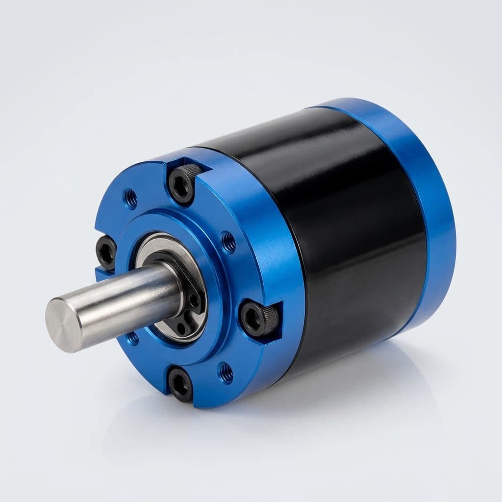
Admittance Versus Impedance Control Architecture Guide
Compare admittance versus impedance control for robotic joints with selector logic, hardware limits, validation tests, and RFQ checks. Request a design review.
When designing joints for a humanoid robot or cobot, choosing the right force control architecture is critical. The debate of admittance versus impedance control isn't just a software problem—it is fundamentally dictated by your hardware's mechanical properties, such as backdrivability, gear ratio, and sensor placement.
Use the interactive architecture selector below to determine the optimal control scheme for your specific robotic joint hardware.
Interactive Architecture Selector
Control Architecture Selector
Screen admittance versus impedance control from the hardware facts that usually decide the architecture: reduction, sensing, compliance, and backdrivability.
Use the output reduction seen by the joint, not just motor gearhead data.
Count joint torque sensors or wrist/end-effector 6-axis F/T sensors.
Describe the mechanical path before software compensation.
Use measured reflected inertia/friction if you have test data.
Best fit for stiff, non-backdrivable hardware that can measure external force and command a position loop.
Conditions and limits
- Use the force signal as the input and output a compliant position reference.
- Keep the inner position loop stiff but monitor contact latency.
- Validate virtual mass/damping against the stiffest expected environment.
Unexpected impacts can arrive faster than the force-sense, compute, and position-track chain can react.
Specify F/T sensor range, noise, and sampling rate before finalizing gearbox and controller tuning.
Treat the selector as an architecture triage tool: it points to the likely control family, the first failure mode to test, and the next hardware decision to confirm before RFQ.
Executive Summary: Key Conclusions
When evaluating admittance versus impedance control, keep these four conclusions in mind. Literature checked on July 24, 2026 supports the causality distinction; the bandwidth ranges below are engineering screening targets that still require actuator-level measurement.
- Hardware dictates the control scheme, not the other way around. You cannot force high-bandwidth impedance control onto a heavily geared, non-backdrivable harmonic drive without severe stability issues.
- Bandwidth and latency boundaries must be validated on the exact joint. Torque-loop impedance can target higher contact bandwidth when the actuator is transparent. Admittance is usually lower because force sensing, filtering, admittance calculation, and inner position tracking happen in series.
- Admittance requires sensors; Impedance requires transparency. Admittance control fundamentally relies on high-quality external force/torque sensors (6-axis F/T). Impedance control relies on backdrivability and torque transparency (e.g., QDD motors with <20:1 gear ratios).
- Safety responses differ fundamentally. Impedance control is physically yielding by nature (like a spring). Admittance control is simulated yielding and is bottlenecked by sensor-to-motor latency during unexpected, high-frequency impacts, making it prone to "bouncing" against stiff environments.
Visualizing the Control Loops
Understanding the signal flow is the easiest way to grasp the difference between these two paradigms.
Admittance Control takes measured force (F_ext) and computes a desired position (X_ref) using an admittance model. A stiff inner position controller then tracks this reference. Best for rigid, high-friction systems with good force sensors.
Evidence and Core Methodologies
1. Admittance Control (Force $\rightarrow$ Motion Causality)
In admittance control, the robot is fundamentally position-controlled. It reacts to forces and yields by moving.
- The Input: The system measures external forces using a 6-axis force/torque sensor or joint torque sensors.
- The Math: The controller applies an admittance model (usually
M*x'' + B*x' + K*x = F_ext) to translate that force into a new desired position. - The Execution: A stiff, high-gain inner position loop drives the motor to that new position.
- Applicability & Limits: Ideal for systems with high friction or high gear ratios (e.g., >50:1 strain wave or cycloidal reducers). These systems are difficult to backdrive, so measured force is converted into a motion command. The serial chain of measure force $\rightarrow$ filter $\rightarrow$ compute $\rightarrow$ actuate position limits contact response and must be measured on the real drive.
2. Impedance Control (Motion $\rightarrow$ Force Causality)
Introduced fundamentally by Neville Hogan (1985), impedance control treats the robot as an equivalent mass-spring-damper system.
- The Input: The system calculates the error between the desired trajectory and the actual position.
- The Math: The controller applies an impedance model (
F_cmd = K(x_des - x) + B(x_des' - x')) to compute a required restorative force. - The Execution: The motor driver directly applies this calculated torque (often using Field Oriented Control and current sensing).
- Applicability & Limits: Ideal for direct drive or quasi-direct drive (QDD) systems (e.g., planetary gears <20:1). Low friction makes motor current a more useful output-torque proxy, enabling faster force interaction than a sensor-to-position admittance chain when torque calibration and damping are done correctly.
What the Selector Is Actually Testing
| Selector Input | Why it matters | If the answer is weak |
|---|---|---|
| Gear ratio | High reduction raises friction, reflected inertia, and torque estimation error. | Bias toward admittance or add direct output torque sensing. |
| External F/T sensing | Admittance needs measured external force as its input. | Do not rely on admittance unless another force estimate is validated. |
| Physical compliance | Mechanical compliance changes impact energy before software reacts. | Add damping, SEA, current limits, or contact-state logic. |
| Backdrivability | Impedance assumes transparent mechanics between motor torque and output force. | Treat current-only torque control as high risk and measure output torque directly. |
The selector intentionally shows boundary and instrumentation gap states. Those states are not failures of the tool; they are the cases where a procurement or controls team should pause before selecting motors, reducers, sensors, and drive electronics.
Selector Output to Validation Record
Do not copy the selector answer into an RFQ as a final decision. Convert it into a validation record that a supplier or controls team can reproduce on the actual joint. Pair this table with the humanoid joint RFQ checklist before freezing a motor, reducer, encoder, or force-sensor package.
| Selector result | Evidence to request | Stop condition before procurement |
|---|---|---|
| Admittance candidate | Force/torque sensor sample rate, filter delay, inner position-loop rate, and hard-contact step traces. | Do not approve if sensor-to-motion latency makes the joint bounce against the stiffest expected environment. |
| Impedance candidate | Current-to-output-torque calibration, backdrivability measurement, damping tune, and free-space/contact transition logs. | Do not approve if current control cannot predict output torque across load, temperature, and friction range. |
| Boundary case | Side-by-side admittance and impedance bench tests at the same payload, contact stiffness, drive voltage, and thermal state. | Do not approve from theory alone; require measured closed-loop bandwidth and impact traces. |
Quantitative Comparison and Risk Trade-offs
| Comparison Dimension | Admittance Control | Impedance Control |
|---|---|---|
| Control Causality | Force in $\rightarrow$ Motion out | Motion in $\rightarrow$ Force out |
| Bandwidth screening target | Often constrained by F/T sensing, filtering, virtual admittance, and inner position tracking. Use ~20-30 Hz only as an early screening target. | Can target faster interaction when torque/current control is transparent. Use >100 Hz only as a hardware validation target. |
| Hardware Suitability | Harmonic Drives, High-ratio Cycloidals (>50:1) | Direct Drive, QDD (<20:1), Cable-driven |
| Backdrivability Need | Low (Handles non-backdrivable well) | High (Requires mechanical transparency) |
| Sensor Dependency | High (Requires F/T sensors) | Low (Can use motor current / proprioception) |
| Impact Handling | Risky when the position loop reacts after impact force has already risen. | Better suited to fast contact when current/torque limits and damping are validated. |
| Stability Risks | High in hard contact (Stiff environments cause bouncing) | High in soft/unconstrained space (Low damping leads to oscillation) |
| Best validation test | Step contact into the stiffest expected environment while logging force sensor latency and position error. | Torque/current calibration, free-space damping, and contact transition tests at representative load and temperature. |
Contextual Risks & Mitigation Strategies
1. High-Frequency Impact (Legged Robotics / Locomotion) If you are building a legged robot that experiences harsh, sudden impacts with the ground, pure admittance control is highly risky. The latency of the sensor-compute-actuate loop cannot react fast enough to protect rigid gearboxes from shock loads. Impedance control (or mechanical compliance like Series Elastic Actuators) is strongly recommended for impact-heavy applications.
2. Stiff Environment Interaction (Precision Assembly/Machining) When a robot makes contact with a rigid surface (e.g., metal-on-metal insertion), admittance control often struggles with stability ("bouncing"). The delay in force sensing and position tracking causes the controller to overshoot. Mitigation: Lower the virtual mass and increase damping in the admittance model, though this makes the robot feel sluggish.
3. Unconstrained Space (Free Space Motion) Impedance control can become unstable or underdamped in free space if not tuned correctly, because it relies on the environment to provide counter-forces. Mitigation: Controllers often implement a hybrid approach—stiff position control in free space, smoothly blending into impedance control upon contact detection.
Evidence Scope, Sources, and Limits
This report was reviewed on July 24, 2026. The sources below support the control-causality framing and the known stability/passivity concerns. The bandwidth numbers in this page are not universal standards; they are early architecture screening targets that must be replaced by measured data from the selected actuator, drive, sensor, controller rate, and contact fixture.
- Hogan, N. (1985). Impedance Control: An Approach to Manipulation: Part I - Theory. Journal of Dynamic Systems, Measurement, and Control. ASME DOI: 10.1115/1.3140702.
- Keemink, A. Q. L., van der Kooij, H., & Stienen, A. H. A. (2018). Admittance control for physical human-robot interaction. The International Journal of Robotics Research. DOI: 10.1177/0278364918768950.
- Design-screening assumption used here: admittance contact response is penalized by external force sensing, filtering, virtual admittance integration, and position-loop tracking; impedance response is penalized by actuator transparency, current-to-torque calibration, damping, and thermal limits. Validate both with closed-loop bandwidth, impact, and hard-contact stability tests.
Decision Limits and Procurement Checklist
Before choosing a joint module for admittance versus impedance control, ask for these data points from the actuator supplier:
| Procurement Data | Why it matters for control choice |
|---|---|
| Gear ratio, reflected inertia, and no-load friction | Decides whether current-based output torque can be trusted. |
| Encoder placement and resolution | Output-side sensing helps detect compliance, backlash, and contact transitions. |
| Force/torque sensor sampling rate, noise, and overload capacity | Determines whether admittance can react quickly enough without noisy motion. |
| Current-loop rate, torque constant, and calibration method | Determines whether impedance torque commands represent real output force. |
| Continuous and peak thermal limits | Prevents virtual stiffness tuning from exceeding safe motor or driver operation. |
| Contact validation fixture and log format | Makes the selector result auditable instead of a theoretical preference. |
Next Steps for Your Hardware Sourcing
Choosing between admittance versus impedance control dictates your BOM (Bill of Materials). If you choose admittance, you must budget for high-resolution force sensors and stiff gearboxes. If you choose impedance, you need high-torque-density motors and transparent, low-ratio gearboxes.
If you are currently evaluating hardware for your next robotic platform, we can help you align your mechanical constraints with your control software goals.
- Email us: [email protected]
- WhatsApp: Request an engineering sales review
(Looking for broader context? Read our comprehensive guide on Impedance Control in Robotics, or compare the older terminology variant admittance control vs impedance control.)
FAQ: Admittance Versus Impedance Control
What is the shortest practical difference?
Admittance control measures force and outputs motion. Impedance control measures motion error and outputs force or torque.
When should a high-ratio humanoid joint use admittance?
Use admittance when the reducer is stiff and non-backdrivable, and when a reliable F/T sensor can provide the force input. Without that force input, the control loop has little direct evidence of contact force.
When should a low-ratio QDD joint use impedance?
Use impedance when the actuator is backdrivable, torque/current calibration is reliable, and the drive can command torque with enough bandwidth for the contact task.
Can the architecture be hybrid?
Yes. A common pattern is position control in free space, impedance behavior during fast contact, and admittance behavior when a stiff transmission needs force-guided motion.
Are 20-30 Hz and >100 Hz guaranteed bandwidth values?
No. They are screening values for early discussion. The only defensible value is the measured closed-loop contact bandwidth of your actuator, sensor, drive, and environment.
What is the first test before RFQ approval?
Run a low-energy contact test that logs force, motor current, output position, command latency, and temperature. The test should include the stiffest expected environment and at least one free-space/contact transition.
Author

Categories
More Posts
Humanoid Joint RFQ Checklist for OEM Buyers
What to include in your first RFQ email so quotes are comparable, lead times are believable, and engineering rework is reduced.
DDP, RoHS, and REACH Playbook for Humanoid Joint Imports
A buyer-side execution guide to align delivery terms, compliance files, and shipment release decisions before cross-border dispatch.
Functional Safety in Humanoid Joints: Sourcing for ISO 10218:2025 & ISO 25785-1
Source humanoid robot joints with dual encoders, brakes, and STO for ISO 10218:2025, ISO/CD 25785-1, and safety RFQ reviews.