
Admittance Control vs. Impedance Control: A Hardware Sourcing and Architecture Guide
Compare admittance control vs. impedance control for humanoid joints: sensors, latency, actuator trade-offs, and RFQ checks. Contact Humanoid Joint today.
For robotics engineers and OEM procurement teams, admittance control vs. impedance control is not just a software debate; it decides how a robot physically interacts with its environment, whether a humanoid foot is striking the ground or a cobot arm is assembling a delicate part. The debate almost always comes down to two complementary strategies: Admittance Control versus Impedance Control.
Scope and evidence note (checked 2026-07-24): This guide translates control-theory papers and hardware sourcing constraints into an actuator architecture decision. Public catalog pages are useful for sensor types and specifications, but not for final unit pricing or delivery commitments; confirm those with supplier quotes.
Core Conclusion: Start with Impedance Control (Motion $\rightarrow$ Force) for dynamic legged robots or high-impact humanoid joints only when the actuator stack is backdrivable, torque-controllable, and validated at the target loop rate. Start with Admittance Control (Force $\rightarrow$ Motion) for stiff, highly geared arms or cobots when direct force/torque sensing can close the force-to-motion loop. Mixed architectures are common; the final decision should be proven with contact-transition traces, overload tests, and supplier-level sensor data.
Architecture review path
Send the target payload, impact case, loop-rate target, gearbox ratio, and sensing plan before locking the actuator BOM. We will map the supplier evidence needed for an admittance, impedance, or hybrid control architecture.
1. Executive Summary: The Hardware Divide
Before diving into control theory mathematics, procurement and hardware teams must understand that these two software paradigms dictate the Bill of Materials (BOM).
Impedance Control
- Causality: Senses Position $\rightarrow$ Commands Torque
- Behavior: Acts like a Spring (resists displacement with force).
- Hardware Needed: Highly backdrivable actuators (QDD), low gear ratios, accurate current sensing.
- Cost Driver: High-torque density motors, precise phase-current sensors.
Admittance Control
- Causality: Senses Force $\rightarrow$ Commands Position
- Behavior: Acts like a Damper (yields to force with motion).
- Hardware Needed: Stiff actuators, high gear ratios (Harmonic drives), direct force/torque sensing.
- Cost Driver: F/T sensor selection, calibration, cable routing, overload protection, and supplier lead time.
Evidence and limitation
Admittance control can preserve payload density by keeping stiff, high-ratio gearboxes, but its stability margin shrinks when sensor delay, filtering, and a stiff environment add phase lag. Impedance control can absorb impacts better when the actuator is backdrivable and the torque loop remains stable, but it may trade payload density for lower reflected inertia and mechanical compliance.
2. Evidence Map and Decision Boundary
The comparison below separates source-backed principles from engineering boundaries that must be validated on the selected robot.
| Decision claim | Traceable evidence | Practical boundary |
|---|---|---|
| Impedance control defines a dynamic relation between motion error and force/torque output. | Hogan's 1985 impedance-control paper established the manipulation framing and causality distinction. | The paper does not make every geared joint safe for torque control; the actuator must expose accurate, stable torque behavior. |
| Torque-based Cartesian impedance depends on actuator dynamics, sensing, and model quality. | Ott's work on Cartesian impedance control covers redundant and flexible-joint robots. | High gear ratios, friction, and unmodeled compliance can erase the intended "virtual spring" behavior unless joint torque sensing or elasticity is validated. |
| Admittance control stability is sensitive to virtual mass/damping, delay, and environment stiffness. | Keemink et al. review admittance control for physical human-robot interaction and discuss stability limitations. | Treat loop-rate and filtering values as bench-test requirements, not universal catalog numbers. |
| Series Elastic Actuators can improve force control by measuring spring deflection. | Pratt and Williamson introduced SEA hardware for force-controlled robots. | SEA compliance changes bandwidth, packaging, and peak torque density; it is not a free substitute for full system identification. |
| EtherCAT Distributed Clocks help synchronize distributed drives and sensors. | EtherCAT Technology Group documentation describes the bus and Distributed Clocks mechanism. | Synchronization capability does not guarantee contact-control stability; measure drive firmware latency, sensor delay, and worst-case jitter on the real topology. |
3. Visualizing the Control Loops
The fundamental difference lies in causality: which physical property is the input, and which is the output?
4. Deep Dive: Impedance Control (The Spring)
In Impedance Control, the software algorithm treats the robot like a programmable spring and damper. The user defines a virtual rest position and a stiffness value ($K$). If the environment pushes the robot away from this rest position, the controller calculates the error and outputs a motor torque to push back.
Hardware Prerequisites & Evidence
Impedance control requires the ability to output accurate torque with low enough delay and friction that the programmed spring-damper behavior is visible at the output.
- Low Reflected Inertia: High-ratio harmonic or cycloidal stages can mask output torque through friction and inertia. Quasi-direct-drive designs therefore tend to use lower gear ratios, while higher-ratio joints need joint torque sensing, elastic elements, or model compensation before they should be treated as impedance-ready.
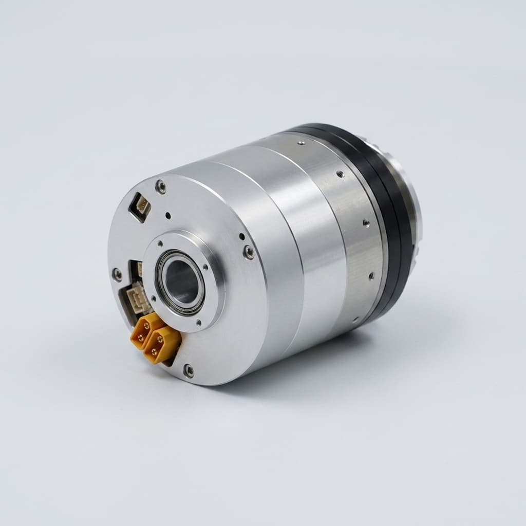
- Actuator Types: Quasi-Direct Drive (QDD) actuators or Series Elastic Actuators (SEAs).
- Sensors: Typically relies on precise motor current sensing (proportional to torque via the torque constant $K_t$) combined with high-resolution dual encoders.
- Validation Target: High-dynamic torque loops are often commissioned around 1 kHz-class sampling, but the acceptance criterion should be measured closed-loop stability, phase margin, and impact traces, not the bus cycle time alone.
Applicability & Boundaries
- Strengths: Strong fit for high-frequency impacts when the mechanical stack is backdrivable enough to avoid hiding contact forces.
- Weaknesses: Lower payload density is common when the design relies on lower gear reduction or added elastic compliance.
- Anti-pattern: Do not attempt pure impedance control on a standard industrial cobot arm with high-ratio gearboxes without a joint torque sensor; static friction (stiction) will cause the joint to feel "sticky" rather than like a smooth spring.
5. Deep Dive: Admittance Control (The Damper)
In Admittance Control, the physical robot is incredibly stiff. The controller actively measures external forces using a sensor and then "complies" by recalculating a new target position, feeding that into a standard high-gain position controller. It behaves like moving a heavy object through a viscous fluid.
Hardware Prerequisites & Evidence
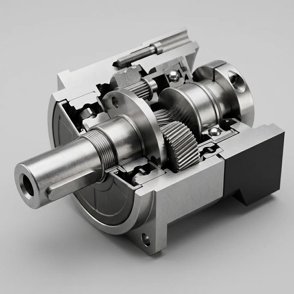
- Stiff Actuators: Standard industrial joints. High gear ratios (100:1 Harmonic Drives, Cycloidal Drives) are preferred because they offer immense payload capacity.
- Sensors: Usually needs direct force/torque sensing at the wrist or end-effector. Joint torque sensing can help, but it must be validated for wrench accuracy after gearbox friction, gravity compensation, and tool payload are included.
| F/T Sensing Option | Evidence to Request | Use Case & Risk Boundary |
|---|---|---|
| Industrial 6-axis F/T sensor | Calibration certificate, rated loads, overload limits, resolution, sample rate, thermal drift data, and quote validity date. | Best fit for precision assembly, polishing, sanding, and contact-rich tooling. Public pages confirm sensor families; final cost and delivery must come from supplier quotes. |
| Cobot-integrated force sensing | Payload-compensation method, filtering settings, external-tool limits, and controller access to raw or filtered wrench data. | Useful for hand-guiding and light process tasks. Verify whether the interface is accurate enough for the intended force-control tolerance. |
| Budget / research sensor | Noise floor, drift over temperature, overload survival, mechanical mounting stiffness, and re-zero procedure. | Acceptable for lab demos and algorithm exploration. Do not treat it as production evidence without environmental and overload validation. |
Applicability & Boundaries
- Strengths: Strong fit for precise tasks where the robot must apply a consistent force against a rigid surface (polishing, sanding, inserting pegs into holes) and for hand-guiding (lead-through teaching).
- Weaknesses: Struggles with sudden, hard impacts.
- Anti-pattern: Committing to admittance-only humanoid locomotion before impact validation. Delay from sensing, filtering, the admittance model, and a stiff position loop can route impact energy into the gearbox unless mechanical compliance, torque limiting, and overload tests prove margin.
6. Network & Latency Evidence (EtherCAT Bottlenecks)
The control loop bandwidth requirements dictate your communication bus choice.
The ranges below are screening targets for RFQ and bench planning. They are not universal guarantees, because sensor filtering, drive firmware, controller scheduling, and mechanical compliance all change stability margin.
| Control Strategy | Screening Target | EtherCAT Bandwidth Requirement | Primary Bottleneck |
|---|---|---|---|
| Impedance Control | 1 kHz-class or faster torque loop where impact bandwidth requires it | High if torque setpoints and state feedback are streamed every cycle | Friction & Motor Inductance |
| Admittance Control | Hundreds of Hz to 1 kHz-class, depending on sensor filtering and surface stiffness | Moderate to high when raw wrench data and position references are synchronized | Phase Lag & Sensor Noise |
RFQ evidence checkpoint
Before asking a supplier to quote, require the loop-rate target, sensor timestamp method, overload case, and torque or wrench evidence to be written into the RFQ package.
7. Architectural Comparison and Sourcing Impact
For procurement and hardware teams, the choice dictates your vendor ecosystem.
| Metric | Impedance Control Architecture | Admittance Control Architecture |
|---|---|---|
| Actuator Type | Quasi-Direct Drive (QDD), SEA | Harmonic Drive, Cycloidal Drive |
| Backdrivability | High (Essential) | Low (Not required) |
| Primary Sensor | High-res Encoders & Phase-Current | 6-Axis Wrist F/T Sensor |
| Impact Handling | Strong when validated on backdrivable torque-controlled joints | Risky for sudden impacts unless compliance and torque limiting are proven |
| Payload/Weight Ratio | Low (Requires larger motors) | High (Leverages gear reductions) |
| BOM Cost Drivers | Custom high-torque-density motors | F/T sensors, calibration fixtures, overload protection, and integration labor |
| Best Use Cases | Humanoid legs, quadruped running | Cobot arms, precision assembly |
8. Risks, Trade-offs, and Caveats
When selecting an architecture, beware of these implementation risks and boundaries:
- The F/T Sensor Drift Bottleneck (Admittance): Admittance control heavily relies on clean force data. If the sensor drifts due to temperature changes or electromagnetic interference, the robot may slowly drift in position (the "ghost movement" effect). Mitigation: Implement deadbands and frequent auto-zeroing routines.
- The "Friction Wall" (Impedance): Trying to run pure impedance control on a highly geared joint without joint-level torque sensors or elastic deflection measurement is usually poor due to Coulomb friction. The software may command a soft "spring," while the physical joint remains rigid.
- Stability Limits / Chatter: Admittance control can go unstable when interacting with highly stiff environments (like a hard metal table) due to control phase delays. Impedance control can go unstable when interacting with very soft environments if the programmed stiffness is too high.
9. Actionable Recommendations by Persona
For Lead Hardware Engineers
- If designing a humanoid leg, do not commit to admittance-only control until drop tests, contact-transition traces, torque limits, and gearbox overload margins are proven. QDDs or SEAs with impedance-style torque control are usually the safer starting architecture for impact-rich locomotion.
- If designing a humanoid arm meant for heavy lifting and precise tool manipulation, use admittance control with a wrist F/T sensor and harmonic drives for maximum payload efficiency.
For Procurement and Sourcing Managers
- Admittance Platforms: Request dated quotes and lead-time windows for 6-axis F/T sensors, calibration services, overload protection, and spare sensor inventory. Public pages are not enough for a production BOM.
- Impedance Platforms: Your supply chain focus must shift to high-quality frameless torque motors and precision phase-current sensors. You will save money on external force sensors but spend more on high-end motor drivers and larger copper windings.
For Robotics Software Engineers
- Ensure your Real-Time Operating System (RTOS) and communication bus can support the measured loop timing budget. EtherCAT Distributed Clocks are designed for distributed synchronization, but the acceptance test should record worst-case jitter, packet loss behavior, sensor timestamp alignment, and closed-loop contact response on the final network topology.
10. Frequently Asked Questions (FAQ)
Foundational Concepts
- Q1: Can a robot use both Admittance and Impedance control?
- Yes, advanced robots use hybrid approaches. A humanoid might use impedance control in its legs for walking (absorbing impact), and admittance control in its arms for precise manipulation tasks.
- Q2: What is "Compliance" in robotics?
- Compliance is the inverse of stiffness. A compliant robot "gives way" when pushed. Both admittance and impedance control are methods to achieve active compliance, albeit through different physical causalities.
- Q3: Are Series Elastic Actuators (SEAs) used for Admittance or Impedance?
- SEAs are often chosen for force and impedance-style control because spring deflection provides a measurable torque signal and physical compliance. They still require bandwidth, damping, and overload validation on the actual joint.
- Q4: Why do many legged robots use impedance-style control?
- Legged robots experience repeated high-frequency foot impacts. Impedance-style torque control over backdrivable or elastic joints can shape contact forces earlier in the mechanical chain than a stiff position loop reacting after impact.
Hardware & Sourcing
- Q5: Does Impedance control require a force sensor?
- No, not necessarily. If the actuator is highly backdrivable, the controller can estimate external forces accurately by measuring motor current (torque) and position errors. However, adding a joint-level torque sensor improves accuracy.
- Q6: Can I implement Impedance control on a standard high-ratio cobot?
- Only if the vendor exposes a stable torque or compliance interface and provides validation data for the required force bandwidth. Otherwise, treat the robot as an admittance or high-level compliance platform rather than a pure torque-controlled impedance actuator.
- Q7: Can we replace an F/T sensor with current feedback in an Admittance system?
- It is very difficult if the gearbox has a high ratio. Friction can mask external force and produce poor force-estimation accuracy. Use direct force sensing unless joint-level torque data has been validated against the required wrench tolerance.
- Q8: How does temperature affect F/T sensors in Admittance control?
- Strain-gauge F/T sensors are highly temperature-sensitive. Thermal drift will register as phantom forces, causing the robot to drift if not frequently re-zeroed or if the deadband is too narrow.
Tuning, Latency & Integration
- Q9: Why does my Admittance controller vibrate when touching a hard surface?
- This is a classic phase lag stability problem. The delay in reading the force sensor, calculating the new position, and moving the motor causes the robot to "bounce" against the stiff surface. Lower the virtual admittance (make it heavier) or increase the control loop frequency.
- Q10: How do I tune the Mass (M), Spring (K), and Damper (B) parameters?
- In Impedance control: high K makes the robot stiff, high B prevents oscillations. In Admittance control: high virtual mass (M) makes the robot feel heavy but stable, while low M makes it highly responsive to human touch but prone to vibration.
- Q11: What is the minimum EtherCAT cycle time for Impedance control?
- Use 1 kHz-class timing as an early screening target for dynamic torque control, then validate the actual cycle time against actuator bandwidth, contact stiffness, sensor timestamps, and worst-case jitter. Some applications will tolerate slower loops; impact-rich legs may need faster inner loops.
- Q12: What happens if the communication bus drops a packet during Impedance control?
- Because impedance control commands raw torque, a dropped packet or latency spike can cause a sudden loss of "springiness" or an aggressive torque jump when the next packet arrives, leading to physical jerks or instability.
Next Steps
Selecting between these paradigms alters the trajectory of your entire robot development program. If you are defining the BOM for your next platform:
- Review the Humanoid Joint RFQ Checklist to ensure your selected actuators support your control paradigm.
- Read our deep-dive on A Unidirectional Series Elastic Actuator Design to understand how hardware springs support force and impedance control.
- Need help sourcing backdrivable joints, harmonic drive modules, or F/T sensor integration? Email [email protected], message WhatsApp +86 18857971991, or use the contact page with your target payload, impact profile, loop-rate target, and preferred actuator type.
References & Verification
- Hogan, N. (1985). Impedance Control: An Approach to Manipulation: Part I—Theory. Defines the foundational causality differences.
- Ott, C. (2008). Cartesian Impedance Control of Redundant and Flexible-Joint Robots. Details torque-based impedance control for redundant and flexible-joint robots.
- Keemink, A. Q. L., et al. (2018). Admittance control for physical human-robot interaction. Reviews admittance-control design and stability constraints.
- Pratt, G. A., and Williamson, M. M. (1995). Series Elastic Actuators. Establishes the SEA hardware concept for force-controlled robots.
- EtherCAT Technology Group. EtherCAT technology overview. Used for the Distributed Clocks and synchronization boundary note.
- ATI Industrial Automation. Force/Torque sensor model specifications. Used as an official supplier reference for industrial F/T sensor selection criteria.
- Robotiq. FT 300-S Force Torque Sensor. Used as an official supplier reference for cobot F/T sensor integration considerations.
Author

Categories
More Posts
Harmonic vs. Cycloidal Drives in Humanoid Joints: Navigating Fatigue Failure
Compare harmonic and cycloidal drives for humanoid robot joints, fatigue risks, shock loads, and supplier checks before selecting durable actuator modules.
How to Audit Manufacturing and QA Before PO Release
A buyer-side field guide for auditing CTQ control, measurement reliability, and lot traceability before committing volume.
In-House Assembly vs. Pre-Integrated Humanoid Joint Modules: A 2026 Scalability & Cost Analysis
A comprehensive 2026 cost and scalability analysis comparing in-house joint assembly against sourcing pre-integrated actuator modules for humanoid robots.