
Crossed Roller Bearings vs. Thin-Section Angular Contact Bearings in Humanoid Robot Joints: A 2026 Procurement and Rigidity Guide
Compare crossed roller and angular contact bearings for humanoid joints: stiffness, friction, and sourcing limits. Use the RFQ checklist to qualify your design.
Crossed roller bearings (CRB) and thin-section angular contact ball bearings (ACBB) offer different ways to support humanoid robot joint outputs. Shortlist a crossed roller ring when combined loads and a tight axial envelope make moment support difficult. Compare a back-to-back angular contact pair when effective bearing spacing, moving mass, and measured drag favor that arrangement. Neither architecture is automatically qualified by its bearing type or joint location.
Reviewed: November 11, 2026. Scope: global OEM sourcing and mechanical architecture for humanoid robot rotary joint actuators. This guide addresses hardware architects, structural engineers, and procurement leads. It compares output support bearings, not the internal motor bearings, reducer torque capacity, or complete robot safety performance.
Evidence and limits: Manufacturer references below support bearing construction and selection principles. The stiffness and energy calculations are transparent hypothetical screening examples, not measured supplier benchmarks or customer test results. This guide contains no verified 2026 price survey, delivery commitments, universal gearbox misalignment limit, or prediction of service life. Obtain model-specific data before releasing a design.
The practical risks are underestimating assembled output compliance and accepting excessive friction without measuring it. Start with a joint load spectrum, an angular deflection budget, and a permissible drag envelope. Then compare complete mounted arrangements against those requirements.
To evaluate custom or catalog actuator options, send your joint load spectrum, moment limits, and hollow-shaft packaging constraints to our engineering team.
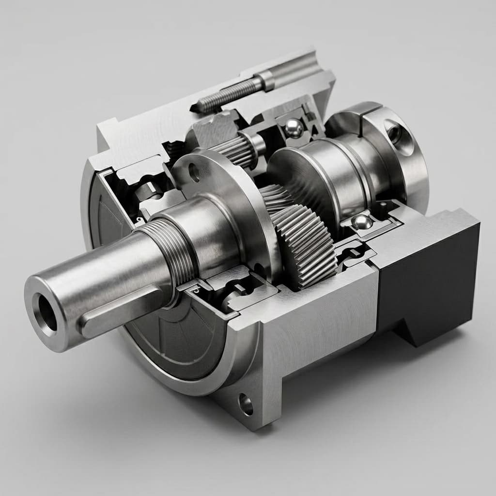
Cover image: illustrative cutaway of a geared shaft assembly with ball bearings and housing. It does not identify a crossed roller bearing, show a validated humanoid actuator design, or provide evidence of bearing performance.
1. The Mechanical Backbone: Why Output Bearings Govern Joint Support
Distinguishing Internal Motor Bearings from Joint Output Bearings
An integrated joint module can contain several bearing subsystems:
- Internal motor and reducer bearings support the rotor, input shaft, wave generator, or planetary elements. Their operating speed and load path differ from those of the output support.
- Main output support bearings connect the stationary housing to the rotating output flange. They react the external link loads that would otherwise pass through components unsuited to structural support.
An output arrangement must be checked for radial force, axial force in both directions, and overturning moment. These are separate from drive torque about the rotation axis. A quoted actuator torque rating does not establish its ability to support a cantilevered limb.
For a perpendicular force, the simple screening relation is M = F × L, with force in newtons, lever arm in meters, and moment in newton-meters. In a real linkage, use the full force vector and its perpendicular offset from the bearing center. Include link weight, payload, acceleration, contact forces, and exceptional events in the load cases.
Illustrative load path, not a dimensional drawing

Stationary housing -> Output bearing -> Rotating flange ---- Link
                            ^                                |
                            |<-- perpendicular offset L ---->|
                                                             v F

Overturning moment at the bearing: M = F × L
Drive torque about the joint axis is a separate requirement.
Do not assign a universal heel-strike force to every humanoid. Robot mass, gait, foot compliance, transmission layout, and contact timing change the loads substantially. Use simulation to establish candidate cases, then correlate the critical cases with instrumented prototype measurements.
2. Contact Mechanics: Cylindrical Rollers, Angular Contact Pairs, and Four-Point Bearings
Crossed Roller Bearings: Orthogonal Rollers in One Ring
A crossed roller ring uses cylindrical rollers with adjacent roller axes perpendicular to each other. THK describes its 90-degree V-groove arrangement as supporting radial, axial, and moment loads in a single bearing. This makes it a useful candidate when a separate, widely spaced bearing pair would exceed the available axial package.
Nominal roller line contact spreads load differently from ball contact. Real loaded contacts have finite areas; roller profiles, raceway geometry, clearance, and ring deformation affect the result. The geometry alone cannot establish a universal stiffness multiplier, load rating, or impact resistance. A thin mounting flange can erase the benefit of a stiff bearing.
Thin-Section Angular Contact Bearings: Compare the Complete Pair
An angular contact bearing supports combined radial and axial loading, with axial capacity oriented in one direction. Opposed bearings provide support in both directions. Back-to-back (DB) and face-to-face (DF) arrangements differ in effective load-center separation and sensitivity to alignment. Compare the actual arrangement, including spacers, retention features, preload, and mounting shoulders.
Effective spacing can improve moment resistance, but it also consumes package length. Thin rings need appropriate support: housing ovality and clamping deformation can change internal clearance and running torque. A small cross-section is a packaging property, not evidence that installation accuracy can be relaxed.
Kaydon's thin-section bearing overview explains the constant-cross-section approach and the available material, lubrication, contact-angle, and precision options. Those options are reasons to compare exact part configurations rather than treating all thin-section bearings as equivalent.
Four-Point Contact Is a Separate Architecture
A four-point contact bearing can carry bidirectional axial and moment loads in a compact arrangement. It is not the same configuration as two opposed angular contact bearings. Its contact state and friction depend on loading and internal fit. Keep it as a third candidate where the supplier supports the application; do not assume it always has lower drag or poorer stiffness than every crossed roller ring.
3. The Tilting Moment Rigidity Dilemma and Gearbox Alignment
Calculate Deflection from a Stated Stiffness
A local linear approximation is theta = M / K_theta, where moment is in Nm and angular stiffness is in Nm/rad. Convert radians to arcminutes by multiplying by approximately 3437.75. Bearing stiffness can vary with load and preload, so identify whether a supplier gives tangent stiffness, secant stiffness, or a full moment-versus-angle curve.
The following calculation uses assumed stiffness inputs only. These inputs are not catalog values, measurements, or evidence of a fixed ranking between bearing types. The common load is an illustrative 150 Nm overturning moment.
| Hypothetical candidate | Assumed stiffness, kNm/rad | Calculation in radians | Calculated tilt, arcminutes |
|---|---|---|---|
| A: crossed roller concept | 600 | 150 / 600,000 = 0.000250 | 0.86 |
| B: compact angular contact pair concept | 150 | 150 / 150,000 = 0.001000 | 3.44 |
| C: four-point concept | 80 | 150 / 80,000 = 0.001875 | 6.45 |
For an assumed project limit of 2 arcminutes, the total support stiffness required at 150 Nm is approximately 150 / (2 / 3437.75) = 258,000 Nm/rad, or 258 kNm/rad. This limit is an example design input, not a permissible misalignment published by a gearbox manufacturer.
Budget for the Mounted Assembly
Bearing, shaft, housing, bolted interface, and test-fixture compliance can all contribute to measured flange tilt. For a simple common-moment load path, angular deflections add; a real branched structure may require an assembly model. Allocate the budget across the actual structure and verify it at the output flange relative to the reducer housing.
Excessive relative tilt can disturb reducer alignment and load distribution. The permissible value depends on the reducer model, installation geometry, and operating load. Ask the reducer supplier which surfaces define alignment and which loaded and unloaded limits apply. A generic bearing guide cannot predict tooth stress multiplication or a failure time for an unidentified gearbox.
For acceptance testing, apply moment in both directions, record flange angle during loading and unloading, and subtract or report fixture compliance. Repeat at relevant temperatures and after the agreed duty test. Hysteresis and residual displacement can matter even when a single stiffness number looks acceptable.
4. The Friction and Backdrivability Trade-Off
Specify Starting and Running Torque Separately
Rotational resistance includes rolling and sliding losses, separator interactions, seals, and lubricant effects. Ball contacts also involve sliding and spin; describing them as pure rolling would overstate their advantage. Starting torque after a dwell can differ substantially from running torque at a specified speed.
Preload can improve support stiffness while increasing drag, but the relationship depends on bearing size, construction, lubrication, and installation. Request torque curves for the exact configuration at cold start, stabilized operating temperature, and representative external loads. Compare candidates with the same seal and grease conditions, or explicitly account for those differences.
A Reproducible Energy Screening Example
Mechanical friction loss is P = sum(T_friction × abs(angular velocity)). For oscillating joints, integrate this expression over the trajectory; average signed speed can approach zero while friction still dissipates energy.
Consider 26 moving axes in a hypothetical 32-DOF robot. The other six axes are excluded from both alternatives and therefore do not contribute to this comparison. Assume constant average absolute speeds, constant resisting torques, and identical motion for both alternatives:
- Twelve leg axes: 1.1 Nm drag at 2.5 rad/s, giving
12 × 1.1 × 2.5 = 33.0 W. - Fourteen arm and torso axes in configuration A: 0.9 Nm at 1.5 rad/s, giving
14 × 0.9 × 1.5 = 18.9 W. - The same fourteen axes in configuration B: 0.25 Nm at 1.5 rad/s, giving
14 × 0.25 × 1.5 = 5.25 W.
The assumed totals are 51.9 W and 38.25 W of mechanical loss. At an assumed constant 78% conversion efficiency, the corresponding electrical demands are approximately 66.5 W and 49.0 W. The difference is 17.5 W, or 35 Wh over two hours. These are arithmetic results from chosen inputs, not measured savings from switching bearing types.
Actual battery consumption also depends on the motion cycle, regeneration, motor losses, controller behavior, and temperature. Measure the mounted assembly before projecting runtime. Lower drag is only useful if the alternative also meets structural and durability requirements.
Backdrivability and Current-Based Torque Estimation
A simplified output torque balance includes gear ratio times motor torque constant times quadrature current, minus inertia, transmission losses, and output bearing friction. State the torque-constant convention and reference shaft when building that model.
Uncertain friction can obscure small external torques and create hysteresis during reversals. It does not establish a universal sensing deadband or prove that every force below breakaway torque is undetectable. Validate residual torque error and backdrive force over speed, temperature, and motion direction with the actual sensors and controller.
5. Engineering Comparison Table for an RFQ
Use this table to normalize supplier responses. It deliberately avoids unsupported class-wide stiffness, friction, price, and lead-time ranges. Each offer should identify the exact bearing, mounting arrangement, and test conditions.
| Selection question | Crossed roller ring | Duplex angular contact pair | Four-point contact bearing |
|---|---|---|---|
| Load arrangement | Radial, axial, and moment support in one ring | Opposed rows provide bidirectional support | Combined-load support in one ring; verify load limits |
| Moment stiffness | Request mounted moment-angle curve | Include effective load-center spacing | Request curve for selected internal fit |
| Axial package | One ring plus retention and support | Include two bearings, spacers, and retention | Include ring, retention, and support |
| Bore and mass | Check actual drawing and supported ring sections | Compare complete pair and shaft mass | Check actual drawing and housing support |
| Breakaway torque | Specify dwell, temperature, seals, and load | Specify pair preload and matching conditions | Specify internal clearance and contact conditions |
| Running drag | Measure across speed and load range | Measure complete mounted pair | Measure under intended combined loads |
| Mounting accuracy | Follow model-specific shoulder and clamping limits | Control alignment, spacing, and fits | Control ring distortion and fits |
| Life and shock | Obtain separate fatigue and static checks | Obtain checks for both bearings | Use supplier combined-load method |
| Preload designation | Record supplier code and physical definition | Record matching method and preload tolerance | Record internal fit and clearance definition |
| Commercial comparison | Dated quote for exact configuration | Include matching and assembly costs | Include required customization costs |
| Supply continuity | Qualify alternate by drawing and test | Qualify pair, spacers, and preload process | Qualify internal fit as well as dimensions |
Discuss the bearing integration requirements for your joint module once the comparison includes the same load spectrum, package, and acceptance conditions for every candidate.
6. Whole-Body Kinematic Allocation Matrix
Joint location helps organize screening; it does not determine the approved bearing. The following matrix gives starting candidates and the condition that must be checked. None of these entries waives detailed sizing or prototype validation.
| Joint group | Dominant concern to investigate | Starting candidates | Qualification question |
|---|---|---|---|
| Hip pitch and roll | Combined stance loads and link bending | Crossed roller ring or adequately spaced AC pair | Does assembled tilt meet the loaded alignment budget? |
| Hip yaw | Axial support, moment, and housing flexibility | Crossed roller ring or opposed AC pair | Is the housing included in the stiffness result? |
| Knee pitch | Linkage-dependent radial load and impacts | Crossed roller ring or supported bearing pair | Do static and cyclic checks cover exceptional loads? |
| Ankle pitch and roll | Foot contact, sealing, and combined moments | Crossed roller ring or paired arrangement | Is the ground-contact spectrum represented? |
| Waist and torso | Payload-induced bending and structural deflection | Crossed roller ring or spaced AC pair | Does the complete torso support meet the deflection limit? |
| Shoulder and elbow | Cantilever reach versus moving mass | Crossed roller ring or thin-section AC pair | Is stiffness sufficient at maximum reach and payload? |
| Wrist and neck | Low drag, package, and cable clearance | Thin-section AC pair or four-point bearing | Are combined-load capacity and reversal drag acceptable? |
| Hands and fingers | Small package and mechanism-specific loads | Miniature ball bearing arrangements | Are retention, contamination, and service access addressed? |
A ball-bearing arrangement can be suitable for a lower-body joint when its geometry and support meet the requirements. A crossed roller ring can also suit an upper-body joint with high cantilever loading. Record the reason for each selection rather than copying a whole-body allocation diagram into the specification.
7. Sourcing and Qualification Checklist for OEM Procurement Leads
Use these eight gates in the RFQ and acceptance plan. Assign numerical limits from your own load cases and supplier-approved design data.
- 1. Exact architecture and load path: Identify the bearing part number, drawing revision, ring arrangement, support spacing, and retention method. Separate output drive torque from radial, axial, and overturning loads.
- 2. Preload and traceability: Request the supplier's clearance or preload definition, tolerance, and measurement conditions. Codes such as C0, C1, or T1 are not interchangeable across manufacturers. Agree on sampling, serialization, and incoming torque checks appropriate to the program.
- 3. Mounted rigidity: Request moment-angle curves in both directions over the required operating range. Identify fixture and housing compliance, temperature, and bolt condition. Tie acceptance to the project deflection budget and reducer installation requirements.
- 4. Precision and fits: Specify radial and axial runout separately, with datums and measurement methods. Use the standard and grade applicable to the selected product; do not assume an ABEC ball-bearing grade automatically defines a crossed roller ring's performance. Obtain mounting flatness, roundness, fit, and bolt-sequence instructions.
- 5. Raceway materials: Request ring and rolling-element materials, heat treatment, hardness verification, and relevant inspection records. Aluminum or titanium housings require an engineered raceway solution, such as suitable hardened steel inserts; they cannot be made equivalent to hardened bearing steel by simply prescribing its induction-hardening process. Validate insert retention and differential thermal expansion.
- 6. Lubrication and seals: Specify temperature range, oscillation angle, speed, contamination exposure, and maintenance access. Have the supplier approve the grease, fill quantity, and seal combination. A generic viscosity or additive recipe cannot guarantee low drag and acceptable wear for every bearing.
- 7. Life, shock, and endurance: Request the applicable rating-life method, load spectrum, equivalent-load assumptions, and static safety check. ISO 281 fatigue-life calculations alone do not establish resistance to impact indentation, fretting, false brinelling, or grease degradation in oscillation. Agree on a representative assembly endurance test and post-test inspection criteria.
- 8. Commercial and alternate-source control: Obtain dated quotations at your sample, pilot, and production quantities. Include tooling, matching, inspection, freight, Incoterms, quote validity, and delivery milestones. Qualify alternatives through drawings and tests; matching bore and outside diameter does not establish drop-in interchangeability.
For a reusable inquiry structure, use the Humanoid Joint RFQ Checklist and attach the bearing-specific acceptance gates above.
8. Sourcing FAQ: Output Bearings in Humanoid Joint Procurement
Why can crossed roller bearings offer high tilting stiffness?
Orthogonal cylindrical rollers provide combined-load support in a compact ring. Their contact geometry can favor stiffness in a short axial package, but the result depends on dimensions, preload, and mounting. Compare model-specific mounted moment-angle curves rather than applying a universal stiffness multiplier.
How does output bearing tilt affect a harmonic drive gearbox?
Relative tilt can disturb reducer alignment and load distribution. The permissible value depends on the reducer model and installation geometry. Obtain the manufacturer's loaded alignment limits; a generic angular threshold cannot predict gear damage or service life.
How much friction torque does a crossed roller bearing add?
There is no reliable class-wide value. Starting and running torque depend on size, preload, grease, seals, temperature, speed, external loads, and mounting distortion. Request measured curves for the exact assembly and compare candidates under the same conditions.
How does bearing friction affect backdrivability and torque estimation?
Bearing drag adds resistance to backdriving and uncertainty to current-based torque estimates, particularly near reversals. Its practical effect depends on the drivetrain, sensors, controller, and temperature. Validate residual torque error on the assembled joint rather than assuming a fixed deadband.
When should thin-section angular contact bearings be shortlisted?
Shortlist them when a supported opposed pair fits the package and meets the required combined loads and moment stiffness with acceptable mass and drag. Wrist, elbow, and other manipulation axes are possible applications, but joint location alone does not qualify the design.
What preload should an OEM specify?
Specify a supplier-defined preload or clearance with its physical meaning, tolerance, temperature, and measurement method. Select it against the project's stiffness, drag, and thermal requirements. Do not transfer a preload code or numerical setting from another bearing family without approval.
What are typical 2026 prices and lead times?
This guide has no verified price survey or delivery dataset. Obtain dated quotations for exact part numbers, quantities, inspection requirements, destination, and delivery milestones. Country of origin alone cannot establish price, quality, availability, or interchangeability.
Can aluminum or titanium joint housings contain integrated raceways?
They can house an engineered bearing or suitable hardened raceway inserts, subject to supplier validation. Do not assume a groove in untreated aluminum or titanium is equivalent to a hardened steel raceway. Check contact durability, insert retention, thermal expansion, and preload across temperature.
9. Sourcing Outlook: Planning 2026–2027 Supply Commitments
Treat 2026–2027 as the procurement planning horizon, not evidence of a verified market shortage. This article does not establish that any supplier has a particular backlog or that a regional alternative delivers a fixed cost saving.
Start qualification while architecture options are still open. Ask suppliers to separate prototype stock, production capacity, and promised shipment dates. A sample available from inventory does not demonstrate repeatable volume delivery, and a catalog listing does not establish reserved capacity.
For a second source, compare drawings, load definitions, preload, lubricant, seals, runout methods, and mounted test results. Keep change-control obligations and requalification triggers in the purchase specification. Changes to a separator, grease, or heat-treatment process can affect performance even if the external dimensions remain unchanged.
Standardize sizes only where the engineering requirements allow it. Consolidating an approved bearing size may reduce spare-part complexity, but forcing every joint into a common diameter can increase mass or compromise support. Compare total installed cost, including assembly, inspection, rework, qualification, and inventory, before selecting a cheaper unit quote.
10. Conclusion and Next Steps
The purchasing decision is whether a specific mounted bearing arrangement meets the joint's loads, alignment budget, drag envelope, and durability requirements. Crossed roller rings offer a compact combined-load architecture. Thin-section angular contact pairs offer another route when support spacing and packaging permit. Four-point bearings remain a distinct candidate requiring their own load and friction checks.
When preparing your next joint module RFQ:
- Define radial, axial, moment, and drive-torque load cases, with motion history and temperature limits.
- Compare complete mounted arrangements using the same deflection, friction, and endurance acceptance conditions.
- Review our Integrated Joint Modules with Brake and Feedback alongside the Humanoid Joint RFQ Checklist.
Contact our engineering team with your load spectrum and interface drawing to discuss bearing options and request available CAD and test documentation for the proposed configuration.
Sources and References
Sources checked November 11, 2026. These public manufacturer pages support the limited principles identified below. They do not validate the hypothetical calculations, establish a gearbox misalignment threshold, or substantiate prices and lead times. Obtain the current model-specific catalog and supplier approval for final sizing.
- THK — Cross-Roller Ring / Double Row Ring. Supports the orthogonal roller arrangement, 90-degree V groove, and radial, axial, and moment load support in one ring.
- Kaydon Bearings — Thin section bearings overview. Supports constant-cross-section product construction and the availability of different materials, lubricants, contact angles, and precision options. It does not specify the performance of an unidentified humanoid joint.
- Kaydon Bearings — Bearing engineering. Describes application-specific design, testing, and life/load analysis resources. Use it to request analysis of the chosen configuration, not as evidence that any candidate has already passed qualification.
Author

Categories
More Posts
Active Short Circuit (ASC) vs. Mechanical Brakes in Humanoid Joints: Sourcing for ISO 13482
Compare ASC vs mechanical brakes for humanoid joints in 2026 sourcing. See SGF, BOM, weight, ISO 13482 limits, and RFQ checks before contacting engineering.
Admittance Versus Impedance Control Architecture Guide
Compare admittance versus impedance control for robotic joints with selector logic, hardware limits, validation tests, and RFQ checks. Request a design review.
Admittance vs Impedance Control: How to Choose for a Robot
Compare admittance vs impedance control by interface, sensing, and contact stability. Use the validation checklist, then request an engineering review.