
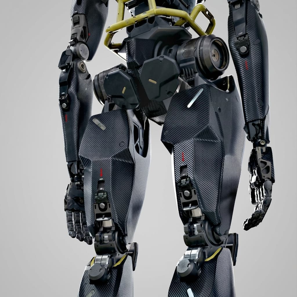
Quasi-Direct Drive (QDD) vs. High-Gear-Ratio Actuators in Humanoid Robots: A 2026 Engineering and Procurement Guide
Compare QDD vs high-gear-ratio humanoid actuators: inertia, thermal limits, sensing and supplier evidence. Use the RFQ checklist to request comparable quotes.
Short answer: Screen Quasi-Direct Drive (QDD) for humanoid joints where low reflected inertia and interaction transparency matter. Screen high-gear-ratio actuators where motor torque multiplication and packaging are priorities. Neither topology guarantees impact survival, low holding power or accurate force sensing: compare the complete joint against the same duty cycle before selecting it.
Reviewed: 29 October 2026. Scope: Global OEM sourcing and mechanical architecture for electric humanoid robot joints. This guide serves robotics architects, actuator engineers and procurement teams evaluating EVT, DVT and pilot-production designs.
Method and limits: This is a literature-based engineering synthesis with explicitly assumed sizing examples and a proposed supplier acceptance process. It contains no first-party hardware test results, supplier qualification results or verified 2026 price/lead-time survey. Its added value is the connected inertia, thermal, sensing and RFQ decision process below. Examples are screening calculations, not product ratings, platform teardowns or safety approval.
Preparing a supplier comparison? Start with the engineering and sourcing RFQ checklist, then request a duty-cycle review with your load history and mounting constraints.
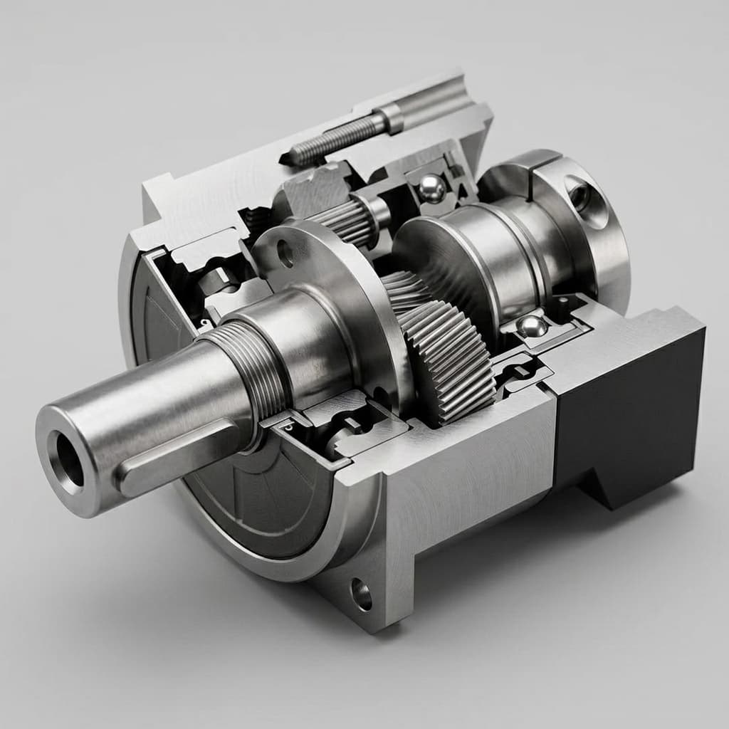
Illustrative imagery only; the image does not identify a gearbox topology or establish actuator performance.
1. Executive Summary: The Structural Divide in Humanoid Actuation
Two useful starting points for architecture screening are:
- QDD: A relatively high-torque motor paired with a low-ratio transmission. This guide uses roughly 5:1 to 10:1 as a comparison range, not a universal definition. Motor geometry and gear layout still determine mass and packaging.
- High reduction: A motor paired with a higher-ratio transmission, such as strain-wave, cycloidal or multi-stage planetary gearing. The 50:1 to 160:1 range here is illustrative; the transmission families are not interchangeable in friction, stiffness or fatigue behavior.
Increasing ratio multiplies ideal output torque by N and reflected rotor inertia by N². Lower reduction can improve mechanical transparency but increases required motor torque for the same load. The resulting thermal burden also depends on motor size and cooling. Treat these as coupled design variables rather than selecting from ratio alone.
2. Mathematical Foundations: Reflected Inertia and Impact Survival
Original calculation schematic using assumed rotor inertias; neither panel is a measured shock-survival result.
The N² Reflected Inertia Scaling Rule
For an ideal rigid transmission, J_ref = N² × J_m, where N is input speed divided by output speed and J_m is rotor inertia in kg·m². This is only the rotor contribution; a full joint model also includes gears, link inertias, compliance and friction.
Consider two hypothetical designs, without claiming equal torque capacity:
- High ratio: N = 100 and J_m = 0.45 × 10⁻⁴ kg·m² gives J_ref = 0.45 kg·m².
- QDD: N = 7 and J_m = 3.20 × 10⁻⁴ kg·m² gives J_ref = 0.01568 kg·m².
The QDD rotor inertia in this example is 7.11 times larger, yet its reflected contribution is 28.7 times smaller. Reproduce this calculation with each supplier's actual rotor inertia and ratio. This number is not a universal transparency multiplier or proof that either design survives a fall.
Impact Mitigation Factor and Dynamic Shock
Wensing et al.'s MIT Cheetah study develops an impact-mitigation metric using a robot dynamics model and demonstrates proprioceptive actuation on a quadruped. It supports considering reflected inertia and passive mechanics alongside force control; it does not establish a universal humanoid shock rating.
During a short contact transient, control bandwidth, latency, structure and passive drivetrain behavior all matter. Higher reduction does not make a transmission an absolute backdrive barrier, and low reduction does not prevent tooth or bearing damage. Accelerating a rotor stores energy; it does not automatically dissipate it. Regeneration depends on the inverter state and the DC bus's ability to accept energy.
Acceptance boundary: specify output torque versus time, impulse repetition, joint posture and load path. A body acceleration expressed only in g cannot determine gear stress. Compare repeated and momentary torque limits separately, then test the mounted assembly.
3. Thermal Dissipation vs. Static Holding: The Joule Heating Trade-off
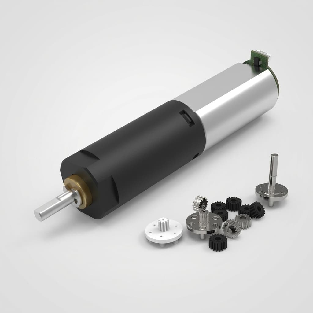
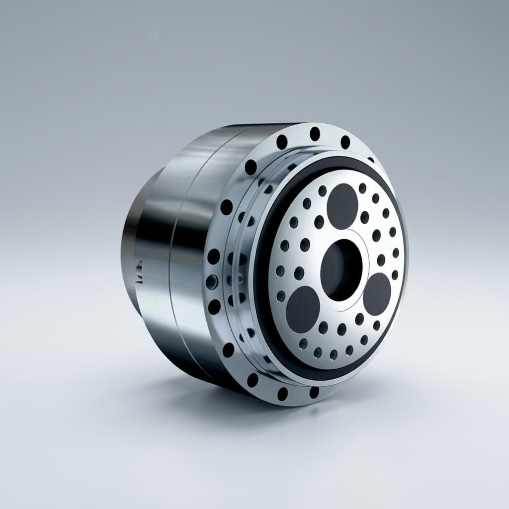
Packaging illustration; no continuous-torque or cooling rating is inferred from the housing.
Motor Constant and Ohmic Losses
Keep the supplier's current and resistance conventions consistent. For a balanced star-connected three-phase motor, P_cu = 3 × I_phase,rms² × R_phase, using phase-to-neutral winding resistance at the stated temperature. A peak-amplitude dq current convention instead gives P_cu = 1.5 × I_q² × R_phase when d-axis current is zero. Line-to-line resistance must not be substituted without conversion.
Define an effective motor constant K_m = torque / √P_cu, in N·m/√W, using matching conventions. Then:
P_cu = (τ_m / K_m)²
For a moving, motoring operating point approximated by τ_out = N × η × τ_m:
P_cu ≈ [τ_out / (N × η × K_m)]²
This isolates copper loss. It excludes gear, bearing, inverter and iron losses. At zero output speed, a running efficiency value does not characterize static friction or holding loss; use measured holding current. The inverse-square ratio trend applies only with the other inputs fixed, which different motor designs rarely satisfy.
A Reproducible Thermal Screening Example
Assume a 60 N·m output demand, η = 0.90 for both moving operating points, and effective K_m values of 0.28 for a 100:1 design and 0.65 for an 8:1 design:
| Assumed design | Required motor torque | Calculated copper loss |
|---|---|---|
| N = 100, K_m = 0.28 | 60 / (100 × 0.90) = 0.667 N·m | (0.667 / 0.28)² ≈ 5.67 W |
| N = 8, K_m = 0.65 | 60 / (8 × 0.90) = 8.333 N·m | (8.333 / 0.65)² ≈ 164.4 W |
These assumed inputs demonstrate sensitivity, not typical actuator power or a prediction for a particular robot. Knee torque depends on posture and ground-reaction geometry, not body mass alone. For a static stance, obtain measured current and winding temperature on the representative mounting structure before claiming an endurance time.
Procurement takeaway: request continuous-torque derating curves with ambient temperature, mounting, cooling and winding limits stated. Compare posture changes, motor resizing, cooling and a suitably rated holding brake. Neither liquid cooling nor a brake is mandatory for every QDD joint. A holding brake's static rating does not establish dynamic stopping capability.
For thermal evidence to request from suppliers, see the humanoid joint thermal sizing guide.
4. Force Sensing and Transparency: Proprioception vs. Dedicated Strain Gauges
Conceptual sensing options, not measured bandwidth or cost comparisons. Both topologies can use either approach.
When Current-Based Torque Estimation Is Useful
A simplified estimate is τ_est = N × K_t × I_q − τ_loss. Here τ_loss is an output-referred lumped correction for transmission losses and, when estimating external interaction torque, internal acceleration effects. A useful observer must characterize direction, speed, load, temperature and hysteresis. A motor-current estimate of generated torque is not automatically the external contact torque.
Lower transmission friction can make current-based estimation useful for interaction control. High-ratio drives can also use calibrated observers; an output sensor may be needed when the required uncertainty or bandwidth cannot otherwise be met. Ratio alone neither mandates nor eliminates strain gauges.
Sourcing and Cost Implications
Compare complete sensing options: transducer, signal conditioning, wiring, calibration, overload protection and software validation. Removing a sensor can lower hardware cost while increasing characterization effort. No universal per-joint saving or bandwidth is claimed here. Require measured torque error across the intended operating envelope, including reversal and acceleration.
5. Granular Architecture Comparison Matrix
The comparison below separates architectural tendencies from the evidence needed to approve a supplier. Numeric example results belong to their stated assumptions; they are not market-wide ratings.
| Engineering and sourcing metric | QDD screening tendency | High-ratio screening tendency | Evidence required for selection |
|---|---|---|---|
| Reduction ratio | Low reduction; roughly 5:1–10:1 in this guide | Higher reduction; 50:1–160:1 comparison range | Exact model, ratio, input speed and output travel |
| Reflected rotor inertia | Lower N² contribution for the same rotor | Larger N² contribution for the same rotor | Rotor inertia and full assembly dynamics |
| Backdrive breakaway torque | Low friction is a design objective | Depends on reducer, preload, seals and lubricant | Cold/hot torque, direction, brake and inverter state |
| Shock tolerance | Low inertia can help impact response | Compliance and torque margins remain critical | Output torque pulse, repetitions and mounted testing |
| Torque density | Motor size may dominate | Reduction can reduce motor torque demand | Same continuous/peak definition and complete assembly mass |
| Static holding power | Check required motor current and heat path | Check holding current, friction and brake power | Measured current, winding temperature and mounting boundary |
| Torque sensing | Current-based estimate is a candidate | Observer or output sensor, per error budget | Calibrated error and bandwidth under representative loading |
| Backlash and stiffness | Gear quality, preload and structure matter | Strain-wave options can have zero backlash | Lost motion, torsional stiffness and hysteresis measured separately |
| Dynamic bandwidth | Reduced inertia can help | Reducer compliance and control affect response | Defined closed-loop test, load, amplitude and filtering |
| Transmission and module cost | Obtain a configuration-matched quote | Obtain a configuration-matched quote | Same inclusions, quantity, tooling and calibration scope |
| Supply lead time | Supplier and configuration dependent | Supplier and configuration dependent | Dated sample/production quote and capacity evidence |
A concrete catalog check helps avoid category errors: the Harmonic Drive CSG-2A table lists CSG-20-100-2A-GR at 52 N·m rated torque, 107 N·m repeated peak, 191 N·m momentary peak and 5 N·m backdriving torque. These are distinct component specifications, not an integrated humanoid joint rating or permission to repeat a momentary overload. Zero backlash also does not mean infinite stiffness or zero hysteresis.
6. Whole-Body Humanoid DoF Allocation Matrix
A hybrid architecture is worth evaluating when joint duties differ. The mapping below is a shortlist for analysis, not a claim about every 2026 platform or a mandatory topology by body region.
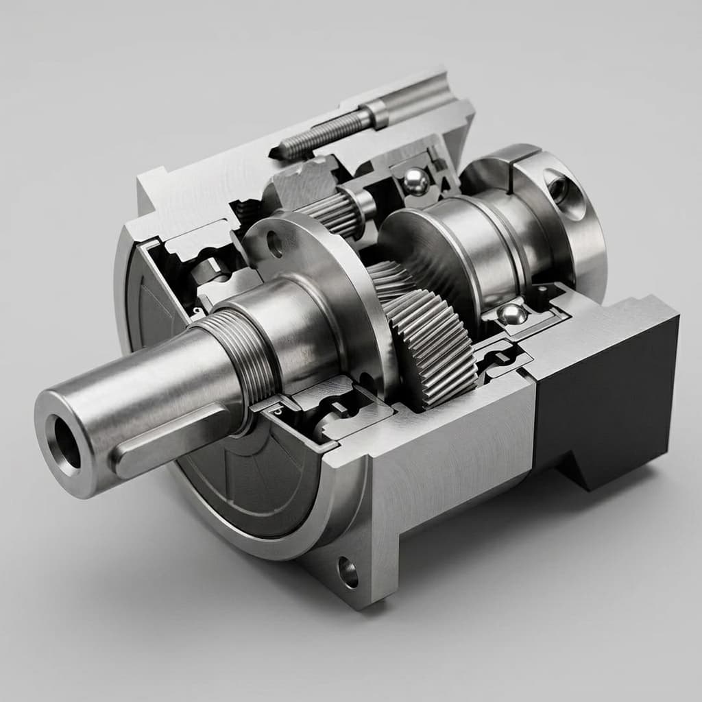
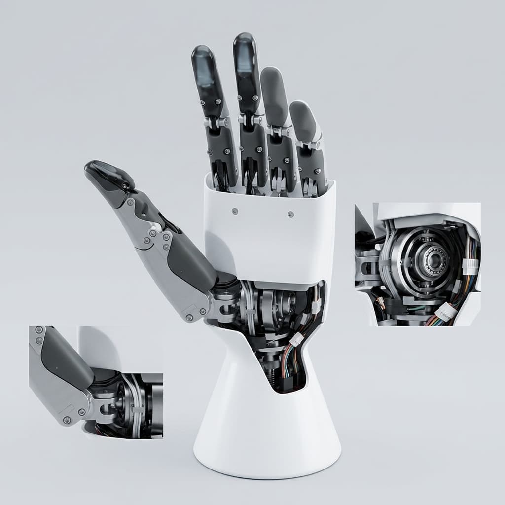
Generic mechanical illustration; a brake, encoder or strain-wave mechanism cannot be verified from this image.
| Joint degree of freedom | Candidate architectures | Selection question |
|---|---|---|
| Hip yaw | Moderate-ratio planetary or higher reduction | Can it meet swing speed, travel and off-axis bearing loads? |
| Hip roll | QDD or a compliant geared assembly | What lateral perturbation torque and power-loss behavior must it tolerate? |
| Hip pitch | QDD, moderate reduction or remote actuation | Which layout meets gait torque-speed demand at acceptable moving mass? |
| Knee pitch | Rotary QDD, higher reduction or linear linkage | What are the posture-dependent continuous torque and impact load path? |
| Ankle pitch/roll | QDD linkage, parallel or remote drive | Can the layout limit distal mass while meeting ground-contact demands? |
| Waist/torso yaw | Strain-wave, cycloidal or planetary | Does payload holding fit the thermal budget and stiffness requirement? |
| Shoulder pitch/roll | High reduction or QDD where interaction matters | Can the selected motor hold the reach load within the radial envelope? |
| Elbow pitch | Compact geared or remotely driven joint | What payload, speed and continuous holding duty must fit the arm? |
| Wrist flexion/deviation/roll | Miniature geared or remote drive | What lost motion, compliance and output feedback does the task allow? |
For planetary packaging specifically, Singh et al. (2025) compare internal and external single-stage layouts using the T-motor U12. Their reported 5:1–7:1 and 7:1–11:1 design regions are conditional on that optimization, not universal gearbox limits.
7. Dynamic Sealing, Thermal Management, and Packaging Trade-offs
Radial Packaging vs. Axial Length
Request full CAD envelopes, including connectors, bearings, seals and cable exits. A low-ratio torque motor may need a larger diameter; a high-ratio reducer may impose axial length or bearing constraints. Neither tendency substitutes for a collision and service-access check across full joint travel.
Dynamic Seal Drag vs. Backdrivability
Seals, lubrication and preload affect both architectures. An ingress-protection target does not mandate one seal design or establish its drag. Measure the assembled joint's cold and hot breakaway/running torque.
For an illustrative output-side seal drag of 1 N·m against 60 N·m commanded output torque, drag is 1/60 = 1.67%, regardless of gear ratio. Do not compare output-side drag directly with motor torque. For an input-side seal, refer its torque through the transmission before comparing it with the joint output. Any lower-friction seal substitution must retain the required ingress performance.
Structural Cooling Conduction Paths
Specify mounting material, contact area, interface resistance and cooling conditions from the thermal model. Validate the representative installation rather than assuming a housing alloy, flatness value or gap-pad conductivity guarantees continuous torque. Use winding sensing or a validated thermal observer with documented trip and derating thresholds.
8. Sourcing Realities: Supply Chain Lead Times, Tooling, and BOM Budgets
There is no verified market-wide 2026 price or lead-time dataset behind this guide. Obtain comparable, dated quotes before choosing an architecture on procurement grounds:
- Normalize scope: distinguish a bare gearset from an integrated motor, bearings, drive, encoders, brake, output sensor, seals and harness. Include calibration and acceptance-test scope.
- Normalize commercial terms: request prototype and production tiers, currency, Incoterms, taxes/duties, tooling/NRE, MOQ, warranty and replacement parts. Compare sample delivery separately from repeat-production capacity.
- Qualify supply: ask for manufacturing location, critical subcontractors, traceability, change control, service support and capacity evidence. A gear family does not establish a supplier's delivery schedule or second-source compatibility.
Use the RFQ checklist below to request a configuration-matched proposal, including the evidence needed to resolve unknown ratings.
9. Quality Assurance and Dyno Acceptance Testing Protocol
This is a proposed qualification process, not a record of tests performed by the publisher. Agree pass/fail limits from your robot requirements and the supplier's approved envelope before testing.
- Backdrive breakaway and drag: use a calibrated torque measurement across approved speeds in both directions, cold and hot. Record brake release, inverter state, lubricant and mounting. Assess speed dependence and hysteresis rather than imposing one friction limit on all QDD joints.
- Current-to-torque calibration: compare the observer output with a calibrated reference transducer over approved continuous and transient operating points. Include reversals, temperature and acceleration. Report normalized error as 100 × (τ_measured − τ_estimated) / τ_rated and also absolute error near zero torque. Set uncertainty and bandwidth limits from the control task; do not automatically sweep to twice rated current.
- Thermal validation: run the defined duty or permitted holding load on a representative structure, logging winding, case and ambient temperatures plus current. Stop at agreed limits; confirm equilibrium or a validated transient model before accepting the continuous rating.
- Load and energy-path validation: apply the agreed output torque-pulse spectrum within an approved fixture and procedure; inspect bearings, gear condition, lost motion and encoder reference afterward. Verify regeneration or dissipation capacity separately from mechanical shock tolerance.
10. Engineering and Sourcing RFQ Checklist
Provide explicit requirements; the supplier must fill unknowns with evidence rather than implied topology-based ratings.
- 1. Kinematic envelope and ratio: joint travel, output speed, acceleration, CAD envelope and permitted ratio range.
- 2. Continuous and peak duty: torque-speed-time history, peak duration and repetition, ambient temperature and continuous holding posture.
- 3. Reflected inertia: motor rotor inertia, ratio and permissible output-referred inertia; include transmission and link contributions in the full model.
- 4. Backdrive friction: breakaway and running-drag limits, cold/hot conditions, direction, seal state and brake/inverter state.
- 5. Impact durability: output torque pulse, duration, repetition count, joint angle and bearing/off-axis loads. Define allowable wear and calibration change; g alone is insufficient.
- 6. Feedback and sensing: motor/output encoder requirements, torque-error budget, calibration, bandwidth and diagnostics. Resolution alone does not establish accuracy.
- 7. Electrical limits: DC voltage range, phase-current convention and duration, regeneration limits, communications and end-to-end control latency.
- 8. Thermal boundary: representative mounting and cooling, winding sensing, continuous derating curves and agreed temperature limits.
- 9. Holding and stopping: power-off load case, brake holding rating, release logic and any separately rated stopping duty; define system fault behavior.
- 10. Batch acceptance: agreed dynamometer checks, dimensional inspection, traceability, sampling plan, records, spares and change control.
11. Frequently Asked Questions (FAQ)
What is the primary physical difference between a QDD actuator and a high-gear-ratio joint?
QDD combines a relatively high-torque motor with low reduction; this guide screens roughly 5:1 to 10:1 against high ratios of 50:1 to 160:1. These are comparison ranges, not universal definitions. Reflected rotor inertia is N² times motor rotor inertia, so compare both inputs rather than assuming a fixed impact advantage.
Do high-gear-ratio actuators inevitably fail during foot strikes or falls?
No. Higher reflected rotor inertia can increase impact impedance, but survival depends on the complete load path, compliance, bearings, gear ratings and control state. Compare joint torque pulses and repetition against the exact supplier ratings, then test the assembly. A body acceleration in g alone cannot establish gear survival.
Can a QDD actuator eliminate dedicated joint torque sensors?
Sometimes. Current-based estimation may meet the control requirement when friction, temperature effects and dynamic errors are characterized. Compare the measured error and bandwidth with the application requirement before removing an output sensor. Neither a low ratio nor a high ratio dictates one sensing architecture or a fixed cost saving.
What is the primary thermal limitation of QDD actuators in bipedal standing?
Low reduction can require more motor torque and winding current for a given output load. Holding loss depends on motor constant, posture and the thermal mounting boundary. Validate continuous torque on the representative structure; cooling, posture changes or a suitably rated holding brake may help. A holding brake does not by itself establish safe stopping.
How should an engineering team allocate QDD versus high-gear-ratio drives across a humanoid robot?
Screen low-ratio drives where interaction transparency matters and high-ratio drives where packaging and sustained torque dominate. Treat each joint independently using its torque-speed history, mass, travel, impact load and thermal limit. A hybrid layout is a candidate architecture, not a rule requiring QDD legs and high-ratio arms.
What lead times and supply chain constraints apply in 2026?
This guide has no verified market-wide price or lead-time dataset. Request dated quotes at the same quantities, configuration, currency and delivery terms. Separate qualification samples from repeat production, and include encoders, brakes, sensors, tooling, calibration, spares and supplier capacity evidence in the comparison.
12. Conclusion and Strategic Recommendation
- Shortlist from the task: use actual joint load histories to compare reflected inertia, thermal demand, packaging and sensing uncertainty. Avoid excluding an architecture solely because the joint is in an arm or leg.
- Resolve evidence gaps: request model-specific gear ratings, measured thermal and backdrive behavior, observer accuracy and configuration-matched quotes. Hold supplier approval until the necessary evidence is available.
- Freeze a qualified assembly: approve the complete mounted module against the agreed duty, impact spectrum, energy path and fault behavior. A hybrid topology is useful only if it meets those requirements.
Before tooling release, use the companion guides for the specific decision you still need to resolve:
- Rotary vs. Linear Actuators for Humanoid Robot Limbs
- Harmonic vs. Cycloidal Drives in Humanoid Joints: Fatigue Failure Analysis
- The Humanoid Joint Thermal Wall: Sizing and Procurement Guide
- Dual-Encoder Humanoid Joints: Procurement and Sourcing Guide
Review Your Actuator Sizing with Humanoid Joint
Contact the engineering sales team with the completed checklist, torque-speed-time history, CAD envelope and expected quantities. Ask which joint configurations can be supported and request the relevant drawings, available dynamometer/thermal evidence, qualification scope and dated pricing before comparing proposals.
Sources and References
Source content reviewed on 29 October 2026. These references support engineering principles and the specifically identified catalog example; they do not substantiate market-wide pricing, delivery times or test results for our products.
- Wensing, P. M., et al. (2017). Proprioceptive Actuator Design in the MIT Cheetah: Impact Mitigation and High-Bandwidth Physical Interaction for Dynamic Legged Robots. Author proof of the IEEE Transactions on Robotics paper, DOI 10.1109/TRO.2016.2640183. Supports the impact-mitigation and proprioceptive-actuation discussion; quadruped results are not humanoid supplier qualification.
- Singh, A., Kapa, D., Chedda, P., and Kolathaya, S. N. Y. (2025). Comparison between External and Internal Single Stage Planetary gearbox actuators for legged robots. Supports the specific motor-dependent planetary packaging comparison in Section 6.
- Harmonic Drive LLC, CSG-2A component-set data. Model-specific ratio, torque, backdriving and stiffness table. Supports the Section 5 catalog example and the need to distinguish rating categories; confirm current conditions with the supplier before procurement.
Author

Categories
More Posts
Humanoid Joint RFQ Checklist for OEM Buyers
What to include in your first RFQ email so quotes are comparable, lead times are believable, and engineering rework is reduced.
A Unidirectional Series-Elastic Actuator Design Using a Spiral Torsion Spring
Screen whether a unidirectional spiral torsion spring is a plausible SEA path, then review evidence, risks, comparison options, and RFQ inputs.
DDP, RoHS, and REACH Playbook for Humanoid Joint Imports
A buyer-side execution guide to align delivery terms, compliance files, and shipment release decisions before cross-border dispatch.