
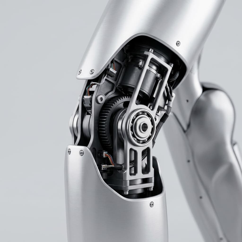
Dual-Encoder Humanoid Joints: Procurement, Safety, and Impact Resilience Guide (2026)
2026 procurement guide for dual-encoder humanoid joints: compare motor-side and output-side feedback, impact resilience, safety risks, and RFQ checks.
As humanoid robots move from sterile laboratory environments into dynamic, unstructured real-world applications like warehouse logistics, automotive manufacturing, and household assistance, the mechanical demands placed on their joint actuators have escalated dramatically. A critical bottleneck that both engineering and procurement teams now face is achieving absolute positional accuracy, force transparency, and impact resilience simultaneously. In 2026, the industry consensus has rapidly shifted away from traditional single-encoder actuator designs in favor of Dual-Encoder Architectures.
For procurement teams and hardware lead engineers, sourcing pre-integrated joint modules is no longer just about specifying peak torque and physical dimensions. The sensor architecture inside the joint dictates the robot's ability to walk stably, handle unexpected collisions, and meet stringent functional safety standards like ISO 13482. If the same joint must deliver active compliance, align the encoder and torque-sensing evidence with the admittance control vs. impedance control architecture decision before freezing the RFQ.
This comprehensive guide breaks down the physical rationale behind dual-encoder architectures, details the procurement and BOM (Bill of Materials) implications, and provides a structured evaluation framework for sourcing next-generation humanoid joint modules.
Scope note (updated July 23, 2026): This guide is written for global OEM procurement and hardware teams evaluating load-bearing humanoid arm and leg joint modules. It does not replace supplier-specific validation, functional safety certification, or full robot risk assessment; confirm torque envelope, brake/STO behavior, environmental rating, encoder diagnostics, and duty-cycle assumptions against your own robot architecture.
1. The Physical Reality: Why Single-Encoder Architectures Fail in Humanoids
In a traditional industrial robotic arm (like those used for automotive welding), a single high-resolution encoder is typically mounted on the rear of the electric motor (the rotor). Because industrial arms are bolted to the floor and built with massive, highly rigid gearboxes (like heavy cycloidal drives), the position of the motor rotor mathematically corresponds to the exact position of the output shaft. If the motor turns 100 degrees and the gear ratio is 100:1, the output shaft has turned exactly 1 degree.
Humanoid robots, however, break this assumption entirely. To save weight and improve energy efficiency, humanoid joint modules utilize ultra-compact, high-ratio strain wave gears (harmonic drives) or lightweight planetary systems. These lightweight gearboxes introduce two unavoidable physical realities:
- Backlash and Hysteresis: Even "zero-backlash" harmonic drives develop mechanical play over millions of walking cycles.
- Torsional Deflection (Compliance): When a 70 kg humanoid robot lands a step, a massive shock load is sent upward through the ankle and knee joints. The metal flexspline inside the harmonic drive actually twists and deforms under this load.
When a single encoder is placed on the motor, it remains completely "blind" to what is happening at the output shaft. The motor might hold its position perfectly, but due to gearbox deflection under load, the actual robotic limb might sag or bounce by several degrees. In bipedal locomotion, an error of just 1 degree at the hip can translate to a 15-millimeter placement error at the foot—enough to cause the robot to lose its balance and fall catastrophically.
2. The Dual-Encoder Architecture Explained
To solve the blindness of the single-encoder system, advanced humanoid joints employ a Dual-Encoder Architecture. This involves integrating two distinct position sensors into a single, compact actuator module:
- Encoder 1: The Motor-Side Encoder (Commutation Encoder). Placed directly on the high-speed rotor of the frameless torque motor. Its primary job is to provide high-speed, low-latency feedback to the Field-Oriented Control (FOC) drive for precise magnetic commutation. It measures the exact angle of the magnetic poles to maximize torque output and efficiency.
- Encoder 2: The Output-Side Encoder (Absolute Encoder). Placed on the low-speed output shaft, after the gearbox. Its primary job is to measure the true, absolute position of the robotic limb in the physical world, entirely independent of any internal gearbox twisting, backlash, or wear.
By simultaneously reading both encoders at incredibly high frequencies (often exceeding 10 kHz), the joint's internal motor controller can instantly calculate the difference between the expected position and the actual output position. This mathematical difference, known as the deflection angle, is the key to advanced humanoid locomotion.
3. Impact Resilience, Virtual Clutches, and Overload Protection
Perhaps the most valuable feature of a dual-encoder system is what it allows the software to do regarding impact resilience. Humanoid joints are frequently destroyed not by normal walking, but by sudden shock loads—such as the robot tripping and catching its fall with an outstretched arm, or a foot slamming into an unexpected obstacle.
In a single-encoder system, the joint is rigidly commanded to hold its position. When a shock load hits, the strain wave gearbox absorbs 100% of the mechanical energy. Because the gear teeth are extremely fine, this often results in sheared teeth or a fractured flexspline, resulting in catastrophic failure and thousands of dollars in repair costs.
With a dual-encoder architecture, the joint acts as a proprioceptive force sensor. By multiplying the calculated deflection angle (the difference between the two encoders) by the known stiffness coefficient of the gearbox, the controller instantly knows exactly how much torque is being applied to the joint from the outside world.
If this external torque suddenly spikes past a safe threshold (due to an impact), the internal drive can instantly execute a Virtual Clutch maneuver. The drive intentionally commands the motor to backdrive (yield) in the direction of the impact, dissipating the kinetic energy electromagnetically rather than mechanically breaking the gears. This transition from stiff position-control to compliant force-control happens in milliseconds, safeguarding the hardware during falls and aggressive physical interactions.
4. Optical vs. Magnetic Encoders: Sourcing Considerations
When reviewing vendor specifications for dual-encoder modules, procurement teams will encounter two primary sensor technologies:
Magnetic Encoders
Magnetic encoders utilize a diametrically magnetized disc (or ring) and an internal Hall-effect or MR (Magnetoresistive) IC chip.
- Pros: Highly robust. Immune to dust, grease, moisture, and vibration. Excellent for humanoid knees and ankles that operate near the ground in dirty environments. Extremely compact.
- Cons: Susceptible to electromagnetic interference (EMI) from the high-power frameless motor if not properly shielded. Resolution is generally lower than optical.
- Sourcing Note: Ensure the vendor explicitly details their magnetic shielding architecture. If the motor side and output side both use magnetic rings, ensure cross-talk is mitigated via Mu-metal shielding or physical separation.
Optical Encoders
Optical encoders use an LED shining through a finely etched glass or metal disc onto a photodetector array.
- Pros: Unmatched resolution (often exceeding 20-bit to 24-bit). Complete immunity to electromagnetic interference. Zero magnetic drag.
- Cons: Highly sensitive to mechanical shock (glass discs can shatter). Extremely sensitive to dust and condensation; they require hermetically sealed enclosures.
- Sourcing Note: Often used on the output side to guarantee ultimate precision, while a rugged magnetic encoder handles the high-speed motor commutation. Avoid optical encoders for impact-heavy joints unless specifically rated for high-shock environments.
5. Functional Safety (ISO 13482) and the Redundancy Mandate
Deploying a 70 kg humanoid robot in a space shared with humans (such as a hospital or a factory floor) triggers strict functional safety compliance, governed primarily by ISO 13482 (Safety requirements for service robots) and general machinery directives (ISO 13849-1).
A key requirement in these standards is Performance Level (PL) and Safety Integrity Level (SIL) certification, which heavily penalize single points of failure. If a single-encoder joint module loses its sensor signal due to a severed wire or IC failure, the motor controller might suddenly command maximum torque in a random direction, causing the robot to violently strike a nearby human.
A dual-encoder architecture provides critical hardware redundancy. The motor controller continuously cross-checks the output encoder against the expected motor encoder position. If the difference between the two suddenly exceeds the physical bounds of the gearbox elasticity (e.g., if the motor spins but the output shaft is jammed, or if one sensor's data packet is corrupted), the drive immediately detects an "Encoder Mismatch Fault."
Within microseconds, the drive can trigger a Safe Torque Off (STO) state, cutting power to the motor and safely engaging the holding brake. For procurement teams, sourcing joint modules with built-in, pre-certified dual-encoder redundancy drastically reduces the time and cost required to achieve final system-level CE/UL certification.
6. Procurement Strategy: Cost Impact and TCO
Transitioning from single-encoder to dual-encoder modules naturally expands the BOM. However, the Total Cost of Ownership (TCO) often heavily favors the dual-encoder approach due to reduced R&D calibration time and massively lower hardware failure rates in the field.
Dual-Encoder vs Single-Encoder Joint Modules: Procurement Impact
| Specification / Metric | Single-Encoder Module | Dual-Encoder Module | Procurement & Lifecycle Impact |
|---|---|---|---|
| BOM Cost per Joint | Base Price ($800 - $1,500) | +$150 to +$400 Premium | Direct unit cost increases, but enables high-end bipedal performance. |
| Startup Calibration | Requires limit-switch homing | True Absolute, Zero Homing | Dual-encoder eliminates homing routines, enabling instant recovery after power loss. |
| Gearbox Lifespan | Moderate (Impacts break gears) | Extended (Virtual Clutching) | Massive reduction in warranty claims and field-replacement part inventory. |
| Functional Safety (SIL/PL) | Difficult to achieve PL d | Built-in Redundancy (PL d/e) | Accelerates time-to-market for collaborative/service robot certification. |
| Supplier Ecosystem | Plentiful (Many industrial OEMs) | Limited but growing rapidly | Requires strategic partnerships with advanced robotics drive manufacturers. |
| Internal Wiring | Standard (4-6 data wires) | Complex (8-12 data wires) | Requires high-density slip rings or hollow shafts for internal cable management. |
7. Engineering and Sourcing Checklist for Dual-Encoder Modules
When issuing an RFQ (Request for Quote) for dual-encoder humanoid joint modules, use the following checklist to ensure the vendor's technology aligns with modern bipedal requirements:
- Absolute vs Incremental on Output: Is the output-side encoder a Multi-Turn Absolute encoder? If the robot loses power mid-stride, it must know exactly where its leg is without performing a dangerous homing sequence.
- Internal Latency: What is the loop update rate of the internal controller when processing both encoders simultaneously? Look for minimums of 4 kHz, ideally 10 kHz for dynamic locomotion.
- Thermal Stability: Does the vendor provide documentation on encoder drift across a temperature range of 0°C to 85°C? Torque motors run hot; cheap encoders will lose accuracy as the joint heats up.
- Hollow Shaft Integration: Does the dual-encoder layout still permit a large inner diameter (hollow shaft) for passing power and EtherCAT cables through the center of the joint?
- Built-in Deflection Algorithms: Does the integrated servo drive actively use the dual-encoder delta to suppress vibrations (anti-resonance) and provide torque estimation out-of-the-box?
- EMI Shielding Validation: If using dual magnetic encoders, request the vendor's EMI cross-talk test results under peak current draw.
If you are shortlisting suppliers, send this checklist with your target torque envelope, available axial length, bus protocol, brake/STO requirements, expected impact cases, and annual volume. For a faster starting point, compare those requirements with our humanoid joint module portfolio.
8. Sourcing FAQ: Dual-Encoders in Humanoids
Q: Do we need dual encoders on every single joint of the humanoid?
A: No. Dual encoders are mandatory for the load-bearing lower body (hips, knees, ankles) and the primary shoulder/elbow joints where impact resilience and high-torque transparency are required. Low-torque joints like the wrist roll or finger actuators can safely use single-encoder or tendon-driven architectures to save weight and cost.
Q: Can we just use a single output-side encoder to measure the final position?
A: No. You cannot accurately commutate a high-pole-count frameless torque motor using an encoder placed after a compliant, high-ratio gearbox. The mechanical delay and backlash will cause the FOC algorithm to fail, resulting in extreme cogging, stuttering, and eventual motor stall. You must have the motor-side encoder for commutation.
Q: How does this affect the EtherCAT/CANopen bus traffic?
A: A well-designed integrated joint module processes the dual-encoder math locally on its own microprocessor. It only transmits the final processed data (Actual Position, Estimated Torque, Error Flags) back to the central robot computer via EtherCAT, ensuring the communication bus is not overwhelmed with raw encoder pulses.
Q: Will adding a second encoder make the joint module significantly longer (axial length)?
A: It depends on the vendor's integration skill. Leading manufacturers use ultra-thin PCB-based magnetic ring encoders or customized bearing-integrated encoders that add only 2 to 4 millimeters to the total axial length of the module.
9. Conclusion and Next Steps
The transition to dual-encoder architectures marks the maturation of the humanoid robotics industry. While it introduces a modest BOM premium and requires more sophisticated internal cabling, the dividends in stability, functional safety, and hardware survival during impacts are non-negotiable for commercial deployment.
For procurement and hardware teams, the goal is to source joint modules where the dual-encoder complexity is pre-solved, calibrated, and sealed by the supplier, delivering a clean mechanical interface and a single EtherCAT port to the rest of the robot.
Ready to upgrade your bipedal platform's proprioception?
Our portfolio of pre-integrated humanoid joint modules features native dual-encoder architectures, optimized for hollow-shaft cable routing, absolute startup calibration, and high-bandwidth impact resilience.
Explore Our Dual-Encoder Humanoid Joint Modules →
Sources & References
- HEIDENHAIN. "12 Ways to Optimize Your Robot Design Using Rotary Encoders." Describes dual encoders that measure motor speed and output-axis angular displacement in robotic joints. Available: https://www.heidenhain.us/wp-content/uploads/12-ways-to-optimize-your-robot-design-using-rotary-encoders.pdf
- Synapticon Documentation. "Store Home Position." Notes that output-shaft absolute encoders are needed for restoring home position in dual-loop setups. Available: https://doc.synapticon.com/node/sw5.1/motion_control/operation_modes/store_home_position.html
- ISO. "ISO 13482:2026 Robotics — Safety requirements for service robots." The governing standard for safety requirements in environments shared with humans. Available: https://www.iso.org/standard/83498.html
- Oriental Motor Engineering Notes. "A Closer Look at Oriental Motor's Magnetic Encoders vs Optical Encoders." Compares magnetic and optical encoder trade-offs for robustness, dust, humidity, and magnetic interference. Available: https://blog.orientalmotor.com/a-closer-look-magnetic-encoders-vs-optical-encoders
(Note: Sourcing strategies and pricing brackets in this report reflect projected conditions for the H2 2026 humanoid component supply chain.)
Author

Categories
More Posts
Active Short Circuit (ASC) vs. Mechanical Brakes in Humanoid Joints: Sourcing for ISO 13482
Compare ASC vs mechanical brakes for humanoid joints in 2026 sourcing. See SGF, BOM, weight, ISO 13482 limits, and RFQ checks before contacting engineering.

Research: Humanoid Joint Functional Safety
Draft research on humanoid joint safety
Admittance Versus Impedance Control Architecture Guide
Compare admittance versus impedance control for robotic joints with selector logic, hardware limits, validation tests, and RFQ checks. Request a design review.