
Rotary vs. Linear Actuators for Humanoid Robot Limbs: A 2026 Engineering and Sourcing Guide
Compare rotary vs linear actuators for humanoid robot limbs: torque mapping, roller screw trade-offs, thermal limits and sourcing. Use the 2026 RFQ checklist.
Short answer: Compare rotary vs linear actuators for humanoid robot limbs at the joint output, over the same motion and load cycle. Rotary drives suit compact joints and wide angular travel. Linear linkages can suit limited-travel knees and ankles when their geometry provides the required torque without exceeding screw force, speed or thermal limits. Both options need overload and life validation.
Reviewed: 26 October 2026. Scope: Global; electric humanoid limb actuation. This guide is for hardware engineers, control teams and procurement leads choosing an architecture and preparing an RFQ. Hydraulic systems, dexterous hands and supplier-specific safety approval are outside its scope.
Method and limits: The comparison uses basic mechanics, the primary references listed below and an explicitly hypothetical sizing example. It contains no original hardware test results, audited supplier capacity data or verified market-average prices. Product illustrations do not establish component ratings. The 2026 date identifies this review, rather than a forecast of platform production or supplier availability.
OEMs can consider two broad architectures:
- Rotary joints: A motor drives the joint axis, directly or through a strain-wave, cycloidal or planetary reducer. Check the complete motor, reducer, bearings, sensors, brake and mounting assembly.
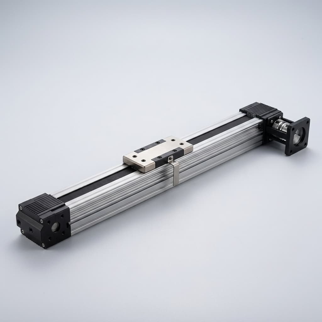
- Mixed rotary and linear joints: Some axes use a motor-driven ball screw or roller screw acting through a crank or parallel linkage. Compare the complete linear actuator and linkage with the equivalent rotary assembly.
For engineering directors and procurement leads, the decision connects packaging, controller integration, installed mass, thermal duty and purchased assembly cost. For a current design, prepare the joint specification for an engineering review using the checklist below.
1. Biomechanics: Start with the Joint Duty Cycle
A linear muscle produces joint rotation through a moment arm. An electric linear actuator can do the same, but its stroke, speed, screw support and transmission geometry impose different limits from biological muscle.
Define joint-angle, velocity and torque histories for stance, swing, lifting, stairs and the intended recovery events. Ground reaction force at the foot is not the same as screw thrust or gearbox torque: map it through the robot geometry and dynamics. Do not assign a universal heel-strike multiplier to every platform.
High-Torque Hinge Joints (Knees and Ankles)
Knee torque depends on stance posture, payload, acceleration and the center of mass. Swing also requires torque to accelerate the limb and overcome losses. A linear linkage can place its larger effective moment arm in a heavily loaded region, provided the remaining travel retains adequate torque and speed.
Ankle pitch and roll may use independent rotary drives or coupled linear mechanisms. For a parallel ankle, evaluate the full multi-axis Jacobian: each actuator can carry combined pitch and roll loads. Include rod-end loads, bearing life and mechanical interference.
Wide-Angle Articulation (Shoulders, Wrists and Pelvic Yaw)
Rotary joints often simplify wide-angle packaging. Linear push rods may need additional links and can encounter toggle positions or collisions. Rotary output is not automatically unlimited: cable routing, hard stops, encoders and brakes can restrict travel.
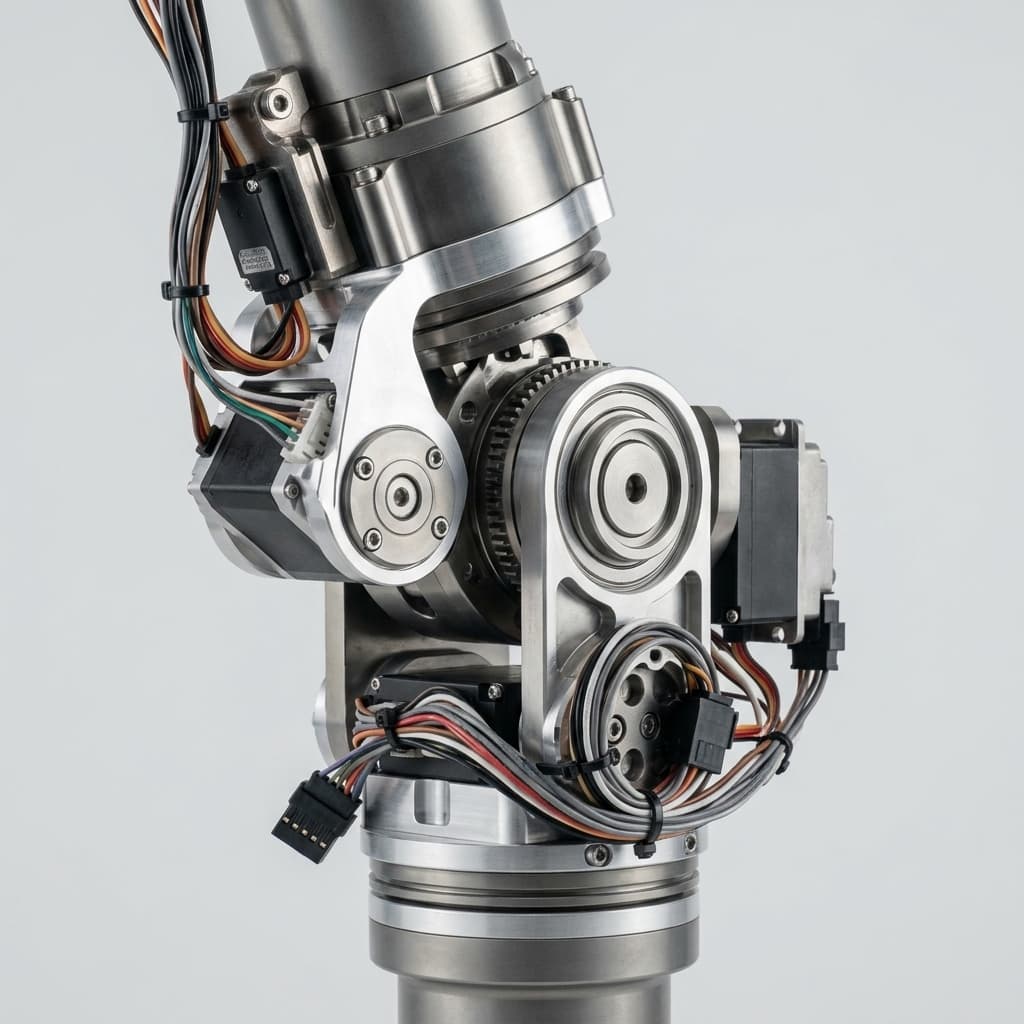
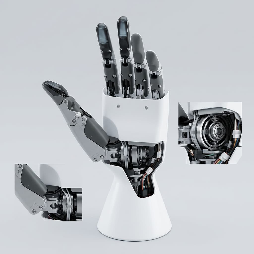
Limb illustration for packaging discussion; it does not identify a validated knee or ankle transmission design.
2. Mechanical Comparison: Kinematics, Shock and Inertia
2.1 Fixed Rotary Ratio vs. Variable Linear Moment Arm
For an on-axis geared rotary joint, a first-pass steady-state relation is τ_joint ≈ τ_motor × N × η_gear, where N is the reduction ratio and η_gear is efficiency. A fixed ratio does not mean constant available torque: speed, current, temperature, friction and structural limits still apply. This mapping supports admittance versus impedance control integration.
For a single linear actuator and crank, use τ_joint = F_axial × r_eff(θ), where r_eff(θ) = r(θ) × sin(φ(θ)) is the perpendicular distance from the pivot to the force line. A direct screw drive has the approximate relation F_axial = 2π × τ_motor × η_screw / p, with screw lead p in metres per revolution. Additional gearing changes the motor-side calculation.
Firgelli's actuator reference also distinguishes joint torque from axial force through a moment arm. These equations are screening relationships; they exclude acceleration and detailed friction. Lin et al.'s knee-actuation paper reports displacement-to-angle modeling and hardware deployment of roller-screw knees. Its public abstract supports feasibility, rather than a universal architecture ranking.
Worked Example: Convert a Joint Requirement into Screw Requirements
Hypothetical inputs: 120 N·m joint torque, 2 rad/s joint speed, 5 mm/rev screw lead, 85% forward screw efficiency, one actuator, no extra gearing. The rows are alternative local moment arms, not measured points on a particular robot. For each row, F = τ / r_eff, v = r_eff × ω, rpm = 60v / p and τ_motor = Fp / (2π × η).
| Effective moment arm | Required axial force | Required linear speed | Screw speed | Motor torque before extra losses |
|---|---|---|---|---|
| 20 mm | 6,000 N | 40 mm/s | 480 rpm | 5.62 N·m |
| 30 mm | 4,000 N | 60 mm/s | 720 rpm | 3.74 N·m |
| 40 mm | 3,000 N | 80 mm/s | 960 rpm | 2.81 N·m |
| 50 mm | 2,400 N | 100 mm/s | 1,200 rpm | 2.25 N·m |
| 60 mm | 2,000 N | 120 mm/s | 1,440 rpm | 1.87 N·m |
| 70 mm | 1,714 N | 140 mm/s | 1,680 rpm | 1.60 N·m |
Decision: A larger moment arm reduces required thrust but increases required linear speed at the same joint speed. Joint mechanical power remains 240 W at these assumed operating points; screw input mechanical power is approximately 282 W before other losses. Electrical input is higher after motor and inverter losses. Check actual geometry, stroke, critical speed, buckling, tension/compression limits, thermal duty and load reversals before selecting a component. This example establishes no shock or service-life rating.
2.2 Impact Loads: Compare Model-Specific Limits
Impacts can load gears, screws, support bearings, rod ends and frame interfaces. A strain-wave drive transfers torque through tooth engagement and a cyclically deforming flexspline. A roller screw transfers axial load through threaded roller contacts. These contact geometries alone do not establish an allowable shock multiplier or life advantage.
Request repeated-peak torque and emergency-stop limits for rotary drives, and static/dynamic axial ratings, support conditions and supplier shock guidance for screws. Dynamic load rating is a fatigue-life parameter, not permission to apply a multiple of that load as an impact. Keep static indentation checks separate from fatigue and transient load analysis. See the related harmonic vs cycloidal joint fatigue guide for additional procurement questions.
For ball screws, Thomson's manufacturer selection resources cover standard and high-load variants, with engineering tools for life, torque, column strength and critical speed. Evaluate the actual model and support arrangement rather than rejecting or approving an entire screw family.
2.3 Mass Distribution and Distal Inertia
Moving mass closer to the hip can reduce swing inertia. A point-mass contribution is I = m × r²; distributed parts require their mass properties and the relevant rotation axis.
Illustrative calculation: Moving a 2.0 kg assembly from 0.45 m to 0.20 m from the hip changes that item's contribution from 0.405 to 0.080 kg·m², a reduction of 0.325 kg·m². This is not a measured reduction in whole-leg inertia or walking energy.
A linear mechanism may allow proximal motor placement, but add the push rod, guides, bearings and brackets to the model. Remote rotary transmissions can also relocate motor mass. Compare installed assemblies using the same trajectory and payload; an inertia reduction alone cannot predict battery runtime.
3. Sourcing & BOM Economics: Rotary vs. Linear
3.1 Quote the Same Purchased Scope
A bare screw, a reducer and a complete joint module are different purchased items. Request assembly prices that include the motor, transmission, support bearings, sensors, brake, drive electronics where applicable, housing, linkage, lubrication and acceptance testing. Separate non-recurring tooling and engineering charges from unit price.
This review has no verified global 2026 price or delivery dataset. Precision grinding, preload assembly, inspection and custom integration can affect availability, but dates and capacity need written supplier confirmation. Request prototype, pilot and repeat-order schedules, quote validity, delivery terms, currency, duties and spare-part support for each manufacturing region.
For precision classes, specify the applicable supplier standard, lead-error metric, reference length and inspection method. Do not treat a C-grade label as a universal guarantee of backlash, stiffness or fatigue life across different screw products.
3.2 Sourcing Comparison Matrix
The six rows below identify evidence to request. They do not rank vendors or provide market-average ratings.
| Actuator type | Packaging and engineering trade-off | Backlash or stiffness evidence | Load and life evidence | Cost and delivery scope to quote |
|---|---|---|---|---|
| Inverted planetary roller screw | Potentially proximal motor; check stroke, support and moving envelope | Axial play and stiffness at specified preload and temperature | Axial ratings, buckling, speed, lubrication and complete linkage cycling | Screw, motor, guides, rod ends, sensors and tooling |
| Precision ball screw | Standard or high-load models; check nut return path and installation | Preloaded axial play, drag torque and thermal growth | Model-specific fatigue, static indentation and support ratings | Screw/nut, supports, lubrication and integrated assembly |
| Strain-wave rotary drive | Compact on-axis integration; check torsional compliance | Lost motion and stiffness under specified torque reversal | Rated, repeated-peak and emergency torque; bearing and flexspline life | Reducer, motor, output bearing, brake and sensors |
| Cycloidal rotary drive | Assess installed mass, diameter and bearing layout | Hysteresis and output stiffness across load range | Eccentric bearing, pin contact and stop-load limits | Complete drive, interfaces and acceptance test |
| Low-ratio planetary / quasi-direct drive | Lower reduction shifts torque and current demand to motor | Gear play, output stiffness and control response | Motor thermal limits, gear/bearing life and backdrive response | Motor, reducer, inverter, cooling and bus requirements |
| Cable / tendon remote drive | Relocates motor mass; requires routing and tension management | Compliance, pretension, hysteresis and drift | Cable/pulley fatigue, wear and inspection interval | Remote motor, routing hardware, assembly and maintenance |
Use this matrix to request a like-for-like actuator review, attaching the load cycle and required purchased scope.
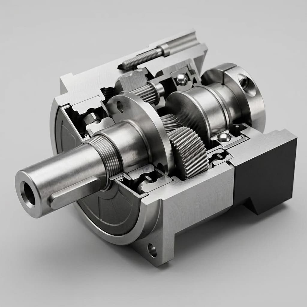
Transmission illustration; brake, encoder, load capacity and service life require a specific assembly drawing and datasheet.
4. Architectural Allocation: Map Each Joint to Its Requirements
These are screening candidates for a design review. Actual torque, force and angular travel must come from the robot's task and geometry.
| Robot joint / axis | Candidate architecture | Engineering reason to consider it | Check before selection |
|---|---|---|---|
| Ankle pitch and roll | Coupled linear pair or compact rotary axes | Can trade packaging, mass location and multi-axis coupling | Full Jacobian, combined loads, collision envelope and foot impact path |
| Knee flexion / extension | Linear crank linkage or on-axis rotary drive | Linear geometry can favor loaded postures; rotary simplifies the ratio | Minimum moment arm, full stroke, stance thermal duty and swing speed |
| Hip pitch | High-torque rotary or linear linkage | Both can supply propulsion and posture torque | Pelvis clearance, range, peak duration and holding behavior |
| Hip roll and yaw | Rotary drives; linkage if packaging permits | Rotary arrangement can simplify wide-angle gimbals | Cross-axis bearings, wiring and singularities |
| Waist / torso | Hollow-shaft rotary or limited-travel linkage | Wide yaw travel favors rotary packaging | Separate yaw and pitch requirements; verify cables and hard stops |
| Shoulder | Compact rotary axes or a remote mechanism | Multi-axis workspace and mass distribution drive packaging | Reach envelope, payload torque, collisions and cable routing |
| Elbow | Compact linear linkage or rotary drive | A limited-travel hinge can support either option | Forearm mass, required speed, pinch points, sealing and service access |
5. Control & Integration Challenges: What Software Teams Must Know
5.1 Non-Linear Kinematics and the Jacobian
For a single-axis linkage, let J(θ) = dx/dθ. Then v = J(θ) × ω and, by virtual work, τ_joint = J(θ) × F_axial. The sign follows the coordinate convention. A small absolute Jacobian means a large force demand for a given joint torque. At a toggle position, this mapping can lose useful torque authority.
Tabulate position, velocity and force limits over the full travel, including tolerances and elastic deflection. Controller update rate is a system design choice; it does not remove a mechanical singularity.
5.2 Sensor Integration: Encoders and Load Cells
A dual-encoder rotary joint can observe motor and output motion separately. Linear assemblies can combine motor position, linear position and direct joint-angle sensing. Choose sensor locations so linkage play, screw lead error and thermal growth are observable where needed.
An in-line load cell measures force at its mounting point. Converting it to joint torque still requires the geometry and an account of friction, inertia and other load paths. Specify calibration, bandwidth, overload, temperature drift and fault detection rather than assuming direct force measurement eliminates all estimation error.
5.3 Power Loss and Stopping
Specify the required behavior for power loss, communication loss and a loaded stop. Check backdriving, brake holding and dynamic stopping ratings, and where regenerated energy can go. The active short circuit and mechanical brake guide provides related design questions; component features alone do not establish system safety compliance.
6. Sourcing & RFQ Checklist for Humanoid Actuators
- Duty cycle: Provide time histories for joint angle, speed and torque, including payload, posture, stance, swing and defined recovery events. State peak duration and thermal boundary conditions.
- Output mapping: For linear drives, provide geometry, the full moment-arm/Jacobian curve, stroke and maximum push/pull force and speed. For rotary drives, state reduction ratio and output load cases.
- Accuracy and preload: Specify lead accuracy, axial or angular lost motion, stiffness, preload and inspection conditions independently. Include rod-end and pivot wear limits.
- Load and life: Request model-specific static, dynamic, repeated-peak and stop ratings as applicable, a life calculation using the actual load spectrum, and representative assembly tests.
- Thermal duty: Obtain continuous and transient performance at the proposed cooling, ambient temperature and enclosure conditions, including screw preload and seal losses.
- Environment and maintenance: Define dust, liquids, corrosion, seal drag, lubrication method, access and replacement intervals. Request relevant test evidence for the proposed assembly.
- Controls and stopping: Define sensors, interface, calibration, force/position limits, fault response, brake behavior and energy dissipation under power loss.
- Commercial scope and capacity: Request dated, itemized prototype/pilot/production quotes, tooling charges, delivery milestones, manufacturing location and evidence of available process capacity.
- Second source and acceptance: Compare interfaces, stroke/lead, sensor scaling, controls and test criteria. Define incoming inspection, change notification and spare-part support; matching mounting holes alone do not establish interchangeability.
7. Frequently Asked Questions (FAQ)
Where should a humanoid use rotary or linear limb actuators?
Linear linkages are candidates for limited-travel knees and ankles when their moment-arm curve, stroke, force and packaging fit the task. Rotary drives are candidates for compact joints and wide angular travel. Neither architecture is mandatory for any joint; compare the complete assembly against the same duty cycle.
Can a precision ball screw replace a planetary roller screw?
Possibly. Compare the actual screw models at the required force, stroke, speed, stiffness, preload, lubrication and life. A roller screw can offer a useful load-capacity option, but screw type alone does not prove impact survival. A ball screw is acceptable only when the supplier ratings and representative assembly tests support the duty.
What changes in the controller when a rotary joint becomes a linear linkage?
A linear linkage has an angle-dependent transmission ratio. Map actuator displacement to joint angle and use the local Jacobian to convert joint torque and speed into axial force and velocity. Check the full travel range, including small moment arms and toggle positions, before setting current, force and motion limits.
How should linear actuators handle power loss and fall protection?
An efficient screw may backdrive when power is removed. Specify the required holding and stopping behavior, brake ratings, release logic and available energy dissipation path. A holding brake and electrical damping have different roles; neither feature alone establishes a controlled stop or robot safety compliance. Validate the assembled system under its defined faults.
Can screw accuracy grade guarantee backlash or service life?
No. Lead accuracy, axial backlash, elastic stiffness and fatigue life are separate requirements. Specify each acceptance limit and measurement condition, including preload, temperature and load direction. Ask for the supplier life calculation and representative cycling evidence; include rod ends, pivots, bearings, seals and lubrication in the assembly assessment.
What price and lead time should buyers assume for 2026 sourcing?
Use dated supplier quotations for the defined assembly and order quantity. Request prototype, pilot and repeat-order schedules, capacity reservations, quote validity, currency, delivery terms, duties and spare-part support. This guide provides no verified global price or lead-time average; compare offers with identical technical scope and acceptance criteria.
8. Conclusion: Choose the Architecture Against the Duty Cycle
Start with rotary actuation where its packaging and fixed ratio fit the required workspace. Consider a linear linkage where its moment-arm curve and motor placement offer a useful trade-off. Keep both candidates until the complete assembly passes force/torque, speed, thermal, overload, life and control checks against the same task.
Review the humanoid joint RFQ checklist, functional safety sourcing guide and thermal duty procurement guide before freezing the platform BOM.
Review Your Actuator Requirements with Humanoid Joint
Contact the engineering sales team with your joint load cycle, packaging drawing, angular travel, target quantity and delivery window. Request a configuration-specific rotary or linear proposal with documented ratings, test evidence and an itemized quote. Confirm offered scope and capabilities during that review.
Sources & References
Sources checked on 26 October 2026. Supplier guides describe their own products and engineering methods; they are not independent tests of every humanoid architecture. No reference below establishes a global price, delivery schedule, universal shock multiplier or guaranteed service life.
- Lin, Y., et al. (2025). Humanoid Locomotion with Roller Screw-Driven Knee Joints: Design, Control, and Deployment. ICIRA 2025, pp. 497–508; first online 27 October 2025. The public abstract reports knee kinematic modeling, simulation and hardware deployment. Full chapter access is restricted; this guide draws no numerical lifetime or cost claim from it.
- Thomson. Ball Screws. Manufacturer resource covering standard and high-load options and selection resources. Used for model-specific sizing considerations, not humanoid field-life evidence.
- Firgelli Automations. Humanoid Robot Actuators: The Complete Engineering Guide. Manufacturer engineering overview. Used here for the distinction between axial force, moment arm and joint torque; its broader platform and market claims are not adopted.
Author

Categories
More Posts
48V vs. 400V Humanoid Joint Architectures: A 2026 Procurement and Supply Chain Guide
Use this 2026 guide to compare 48V and 400V humanoid joint architectures by safety, wiring weight, TCO, supplier risk, and RFQ readiness.
DDP, RoHS, and REACH Playbook for Humanoid Joint Imports
A buyer-side execution guide to align delivery terms, compliance files, and shipment release decisions before cross-border dispatch.
Active Short Circuit (ASC) vs. Mechanical Brakes in Humanoid Joints: Sourcing for ISO 13482
Compare ASC vs mechanical brakes for humanoid joints in 2026 sourcing. See SGF, BOM, weight, ISO 13482 limits, and RFQ checks before contacting engineering.