
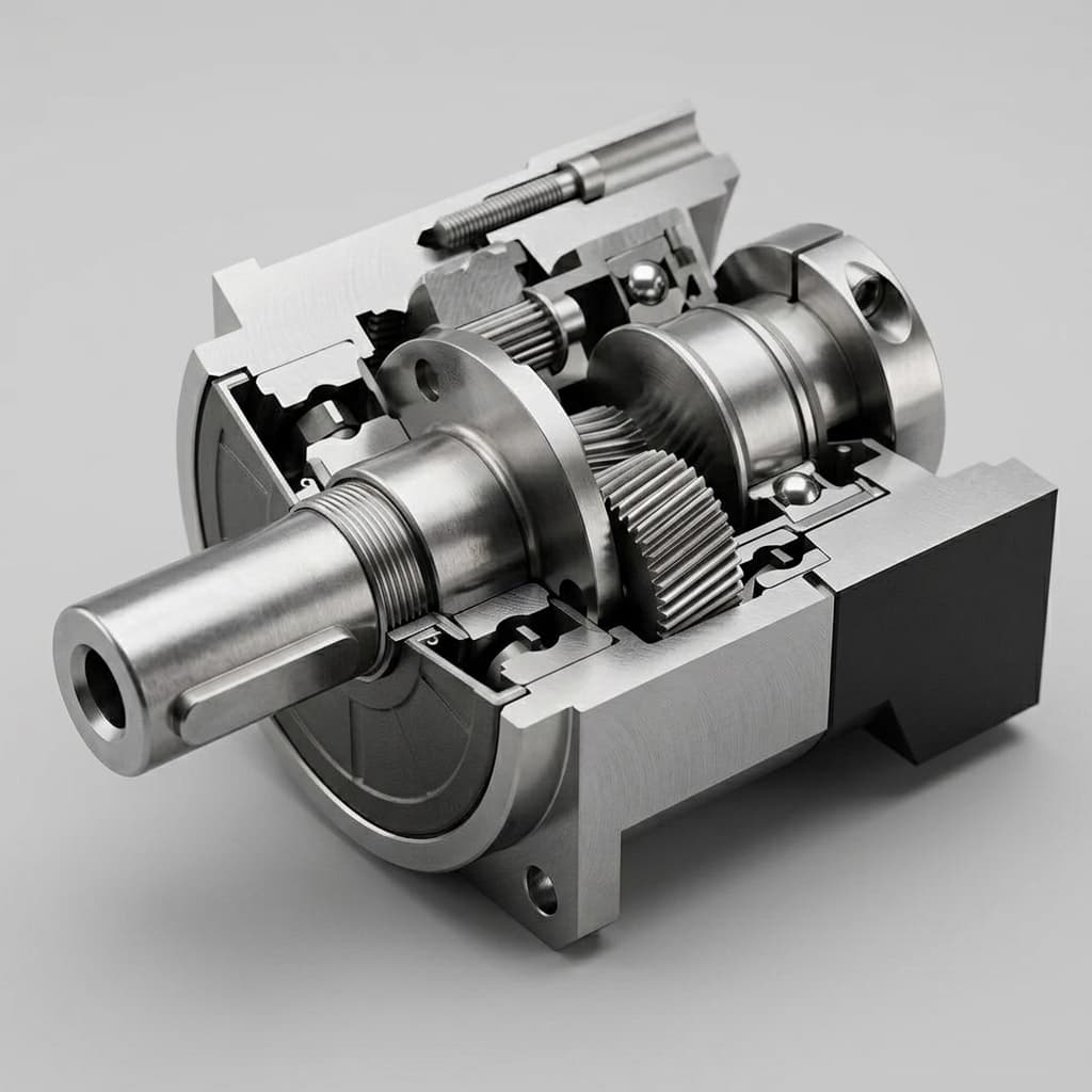
Hollow Shaft (Through-Hole) Humanoid Joints: A 2026 Procurement & Engineering Guide
Procurement guide for hollow-shaft humanoid joints. Compare BOM costs, bearing tradeoffs, and cable routing strategies for 2026 robot architectures.
For global OEMs sourcing hollow shaft humanoid joints in 2026, the procurement question is not only torque density; it is whether the actuator architecture keeps power, STO, encoder, and communication cables alive across millions of repeated joint cycles.
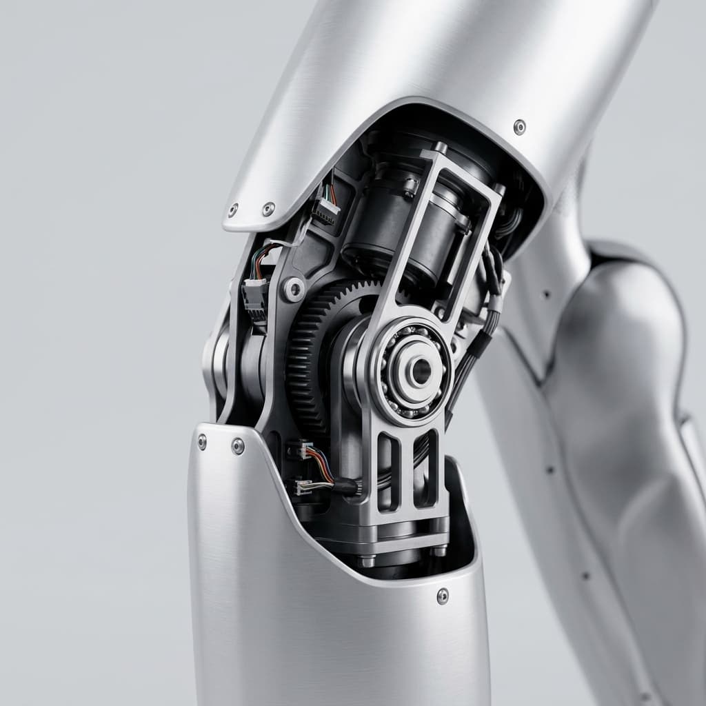
A standard 30 degree-of-freedom (DOF) humanoid robot requires hundreds of internal wires. There are high-voltage DC power cables (often 48V or 400V), low-voltage logic power lines, dual-channel Safe Torque Off (STO) lines, and high-frequency communication buses like EtherCAT or CANopen. Routing these cables from the torso down to the fingertips and toes requires traversing multiple rotating axes (shoulders, elbows, hips, knees).
If an OEM utilizes traditional solid-shaft actuators, these cables must be routed externally around the joint. During the highly dynamic, repetitive motions of walking or lifting, external cables stretch, bend, snag on environmental objects, and eventually suffer copper fatigue failure. In industrial deployments, a single severed EtherCAT wire will trigger a systemic safety fault and crash the robot.
The definitive architectural solution to this problem is the Hollow Shaft (or Through-Hole) Integrated Joint Module. By designing the actuator with a central void, cables can be routed directly down the geometric center of rotation. This practically eliminates cable strain, allows for infinite rotation (when paired with a slip ring), and creates a sleek, snag-free robotic limb.
However, specifying a hollow-shaft joint is not a zero-cost decision. It forces a fundamental reorganization of the joint’s internal components, significantly impacting the Bill of Materials (BOM) cost, thermal performance, and overall outer diameter (OD). For procurement teams and hardware leads, understanding the hidden sourcing implications of the hollow shaft is a critical milestone in platform development.
Scope note: This guide is written for global procurement and engineering teams comparing through-hole versus solid-shaft integrated joints for humanoid prototypes, beta fleets, and early production in 2026. Cost and lead-time ranges are directional planning estimates; final selection still requires supplier drawings, cable-bundle measurements, torque-speed curves, and validation tests.
1. The Geometry of the Hollow Shaft
To appreciate why hollow-shaft joints carry a premium, procurement professionals must understand the cascading physical constraints they impose on the motor designer.
In a traditional solid-shaft joint, the motor's rotor is a solid cylinder. The magnetic flux flows through a relatively small diameter, allowing the overall motor to be compact. The bearings that support the shaft are standard deep-groove ball bearings, which are globally commoditized and incredibly cheap.
When engineers demand a 20mm or 30mm central hole for cable routing, every component must expand outward.
Frameless Motor Scaling
To maintain the same torque output while pushing the rotor outward to create a hole, the frameless motor must increase in Outer Diameter (OD). A motor that was previously 70mm in diameter might grow to 90mm. For a humanoid arm, a 90mm joint might conflict with the industrial design or cause self-collision between the arm and the torso during walking. Alternatively, the engineer can keep the OD small and increase the axial length of the motor, but this pushes the limb segments further apart, increasing the cantilevered load on the robot's structure.
The Harmonic Reducer Redesign
The gear reducer must also accommodate the through-hole. Fortunately, major manufacturers of harmonic and cycloidal drives offer hollow-shaft variants. However, these variants are significantly more expensive and often have longer lead times because the wave generator (the elliptical core of a harmonic drive) must be machined with a large, precision-bored center hole.
2. The BOM Cost Drivers: Why Procurement Pays a Premium
When analyzing quotations for a hollow-shaft joint versus a solid-shaft joint of equivalent torque, procurement will typically observe a 30% to 50% price premium. This is not arbitrary margin padding by the supplier; it reflects genuine material and component cost increases.
Thin-Section Bearings
In a solid shaft, standard, cheap deep-groove ball bearings support the load. In a hollow-shaft joint, the bearings must wrap around the large central hole. This requires Thin-Section Bearings. These bearings have a large inner diameter but a very small cross-section. Because the balls inside are tiny, the bearing's load capacity is lower, meaning the joint must often use multiple thin-section bearings or extremely high-precision (ABEC 7/9) variants to handle the dynamic shock loads of a humanoid walking. Thin-section bearings are vastly more expensive and subject to stricter supply chain constraints than standard bearings.
Absolute Hollow-Shaft Encoders
Humanoids require absolute position feedback for safety and control. A standard solid-shaft joint uses an off-the-shelf magnetic encoder chip placed at the end of the shaft. A hollow-shaft joint cannot use a center-mounted chip. It must use a ring-style encoder—either a large multipole magnetic ring or an optical ring scale that wraps around the through-hole.
Large diameter ring encoders are specialty items. Furthermore, aligning dual encoders (motor-side and link-side) on a large diameter hollow shaft is mechanically complex, increasing the factory calibration time and lowering final assembly yield rates.
The Holding Brake Challenge
As covered in our Functional Safety Guide, humanoids require fail-safe, power-off holding brakes to prevent collapse during a power loss. Designing an electromagnetic brake with a large central void reduces the available surface area for the friction pads and limits the space for the electromagnetic coil. Hollow-shaft brakes are custom-engineered, highly specialized components that drive up the actuator's BOM.
3. Procurement Comparison: Solid vs. Hollow Shaft Joints
To facilitate data-driven RFQ evaluation, the following table compares the physical and commercial realities of both architectures for a hypothetical 100 Nm humanoid knee joint in a 2026 production environment.
| Specification Metric | Solid Shaft Joint | Hollow Shaft (Through-Hole) Joint | Sourcing & Engineering Implication |
|---|---|---|---|
| BOM Unit Cost (Est.) | $1,200 | $1,750 | Hollow shafts carry a ~45% premium due to encoders, thin bearings, and custom brakes. |
| Component Lead Time | 8 - 12 Weeks | 16 - 24 Weeks | Thin-section bearings and ring encoders are critical bottleneck components. |
| Cable Fatigue Life | Low (External Flexing) | Extremely High (Central Torsion) | Hollow shafts drastically reduce warranty claims and field maintenance. |
| Outer Diameter (OD) | ~75mm | ~95mm | Hollow shafts force the mechanical team to accept a bulkier limb profile. |
| Thermal Dissipation | Excellent | Reduced | The central hole removes solid metal mass that previously acted as a heat sink. |
| Assembly Complexity | Low | High | Passing pre-connectorized harnesses through the joint requires careful factory SOPs. |
| Supplier Ecosystem | Plentiful | Limited | Fewer Tier-1 suppliers have mastered compact, high-torque hollow joint integration. |
4. Engineering Boundaries: The Cable Fill Ratio
A common engineering trap is demanding a hollow shaft, but failing to specify a sufficient Inner Diameter (ID) for the cables. Procurement and engineering must align on the Cable Fill Ratio.
If the through-hole is 20mm in diameter, you cannot stuff a 20mm bundle of wires through it.
- Friction & Binding: As the joint rotates, tightly packed cables will grind against each other and the inner wall of the shaft. This friction strips wire insulation, leading to catastrophic short circuits.
- Thermal Expansion: High-current power lines generate heat. Tightly bundled wires cannot dissipate this heat, leading to localized melting.
- Connector Passage: If the cables are pre-terminated with connectors (e.g., Molex, JST, or custom M8 headers) at the harness factory, the through-hole must be large enough to allow the connector to pass through during final robot assembly, not just the wire.
Engineering Best Practice: Target a maximum 50% to 60% fill ratio. If the total cross-sectional area of the wire bundle is 150 mm², the joint's through-hole area must be at least 300 mm² (approx. 19.5mm diameter).
5. Hollow Shaft Joint RFQ Checklist
When drafting the RFQ for a humanoid platform, procurement teams should use this checklist to ensure the hollow-shaft requirements are strictly defined, preventing costly mid-cycle redesigns:
- Specify the Minimum Inner Diameter (ID): Has the electrical team provided the exact bundle diameter, including the width of the largest pre-terminated connector?
- Request Continuous Rotation Specs: Does the joint need to rotate infinitely (360°+)? If so, you cannot simply pass wires through the hole; you must mandate the integration of a Slip Ring inside the hollow shaft.
- Verify Bearing Load Ratings: Because thin-section bearings are used, demand the dynamic axial and radial load limits from the supplier to ensure they can survive the robot's jumping/walking impact loads.
- Audit the Encoder Sealing: Large diameter ring encoders are highly susceptible to dust and magnetic debris. If the robot is deployed outdoors, ensure the internal hollow shaft is IP67 sealed from the encoder chamber.
- Check Thermal Derating: Does the supplier's rated continuous torque assume a solid metal mounting block? Ask for thermal derating curves specific to the hollow-shaft model.
6. Sourcing FAQ
Q: Can we use a solid shaft for the arms and a hollow shaft for the legs? A: Yes. Many OEMs take a hybrid approach to optimize BOM costs. The legs, which carry heavy current for 400V locomotion and endure aggressive dynamic movement, utilize hollow shafts. The arms, which may run on 48V and handle lighter payloads, use cheaper solid-shaft joints with external cable routing.
Q: If we use a hollow shaft, do the cables twist and break inside? A: If the joint has hard mechanical stops (e.g., a knee that only bends 150 degrees), the cables undergo simple torsion along the central axis, which induces virtually zero strain on the copper. If the joint rotates continuously (e.g., a radar head or an infinitely spinning wrist), the wires will snap unless a slip ring is installed inside the hollow shaft.
Q: Are hollow-shaft harmonic drives structurally weaker? A: Yes, marginally. The removal of central material reduces the stiffness of the wave generator. However, top-tier reducer manufacturers compensate for this with advanced metallurgy and modified elliptical profiles. The larger constraint is usually the bearing capacity, not the gear teeth.
Q: Does IP67 sealing increase the cost of a hollow-shaft joint? A: Significantly. Sealing a solid shaft requires one rotary lip seal on the output. Sealing a hollow shaft requires sealing the outer housing and the inner through-hole, doubling the number of dynamic friction seals. This adds cost, increases parasitic friction, and reduces backdrivability.
7. Conclusion: The Value of Seamless Integration
The decision to adopt hollow-shaft joints is an acknowledgment that a humanoid robot is a complete system, not just a collection of motors. While the initial procurement cost is higher, the elimination of external wire harnesses radically improves the robot's reliability, aesthetic appeal, and MTBF (Mean Time Between Failures) in the field.
For hardware teams, the challenge is finding a supplier capable of densely packing dual ring encoders, fail-safe brakes, and high-torque frameless stators around a generous central through-hole, without expanding the joint OD beyond acceptable limits.
Are you defining the cable routing architecture for your humanoid platform? Our engineering team specializes in ultra-compact, high-torque integrated joints with generous through-holes designed specifically for dense bipedal wire routing. Whether you need bare hollow-shaft actuators or fully integrated slip-ring solutions, we can support your 2026 prototyping and scaling needs.
Submit your Cable Fill and Torque Requirements for a Custom RFQ →
Sources & References
- Kollmorgen. "Frameless Motor Design Guide." Used for frameless motor packaging principles and trade-offs when motor geometry changes around a central through-hole. Available: https://www.kollmorgen.com/en-us/developer-network/frameless-motor-design-guide
- Robotics Tomorrow. Robotics industry coverage and integration context for multi-axis robot cable routing, field reliability, and automation supplier practices. Available: https://www.roboticstomorrow.com/
- IEEE Spectrum Robotics. Robotics manufacturing and humanoid market coverage used for high-level supply-chain context; article-specific cost and lead-time numbers in this guide are planning estimates, not quoted market indexes. Available: https://spectrum.ieee.org/robotics
(Note: Pricing and lead-time ranges are directional planning estimates for medium-volume procurement of humanoid joint actuators in 2026.)
Author

Categories
More Posts
48V vs. 400V Humanoid Joint Architectures: A 2026 Procurement and Supply Chain Guide
Use this 2026 guide to compare 48V and 400V humanoid joint architectures by safety, wiring weight, TCO, supplier risk, and RFQ readiness.

DDP, RoHS, and REACH Playbook for Humanoid Joint Imports
A buyer-side execution guide to align delivery terms, compliance files, and shipment release decisions before cross-border dispatch.
Dual-Encoder Humanoid Joints: Procurement, Safety, and Impact Resilience Guide (2026)
2026 procurement guide for dual-encoder humanoid joints: compare motor-side and output-side feedback, impact resilience, safety risks, and RFQ checks.