
EtherCAT vs. CAN FD vs. Single-Pair Ethernet (100BASE-T1) in Humanoid Robot Joint Actuators: A 2026 Sourcing, Harness Mass, Latency, and EMC Guide
Compare EtherCAT, CAN FD and 100BASE-T1 for humanoid joints: calculate latency and harness mass, check EMC limits, and prepare a supplier RFQ with evidence.
EtherCAT vs. CAN FD vs. Single-Pair Ethernet is a comparison of both protocol and physical layer. CAN FD is a shared-bus communication technology; EtherCAT is an industrial Ethernet protocol; 100BASE-T1 is a 100 Mbps single-pair Ethernet physical layer. An EtherCAT implementation can use a compatible 100BASE-T1 design, so SPE and EtherCAT are not mutually exclusive choices.
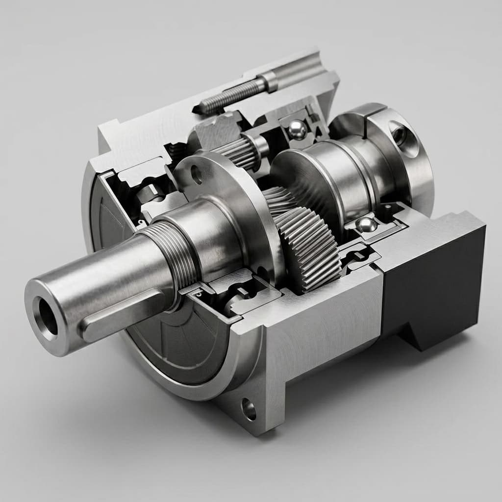
Reviewed: November 8, 2026. Scope: global OEM sourcing of integrated humanoid joint actuators. This guide addresses motion architects, electrical and mechanical engineers, and procurement teams comparing communication interfaces. It uses a reproducible 32-axis traffic example and a separate illustrative harness calculation. These are engineering estimates, not measured robot performance, supplier quotations, conformance reports or safety approvals. The cover image is a mechanical illustration; it does not identify a tested communication board.
Choose CAN FD when the measured local traffic schedule and gateway delay meet the task. Use qualified 100BASE-TX EtherCAT as a baseline when coordinated cyclic motion and available drive support matter. Evaluate EtherCAT with 100BASE-T1 when communication cabling is a demonstrated packaging constraint and the supplier can prove controller/PHY compatibility. Do not replace a working network solely because a thinner cable is advertised.
For an initial sourcing discussion, send the joint count, cycle time, payload map and routing drawing with your RFQ. Those four inputs make proposed interfaces easier to compare than a protocol name alone.
1. The Physics of Joint Communication: Multi-Axis Bandwidth and Latency Math
Separate network updates from local servo loops
A 1 kHz command exchange does not mean that the motor current loop runs at 1 kHz. Current regulation can execute locally at a different rate while the network carries torque, position or velocity targets. Specify network period, acceptable command age, sampling time and actuator execution time separately. Distributed clock accuracy also differs from packet latency and closed-loop response.
For this example, assume 32 axes, one 16-byte command and one 24-byte feedback payload per axis, every 1 ms. The command could contain a controlword, target torque, position and offsets; feedback could contain status, position, velocity, torque and diagnostics. This is an illustrative application mapping, not a mandatory CiA 402 packet. Safety-related traffic requires its own appropriate implementation and budget.
CAN FD: count both directions and protocol overhead
CAN FD supports payloads up to 64 bytes, but command and feedback normally come from different transmitters and require separate frames. A terminated trunk with controlled stubs is the starting topology; a passive star is not an automatic substitute. The achievable nominal and data-phase rates depend on transceivers, cable length, stubs and signal integrity.
At an assumed 5 Mbps data-phase rate, the payload-only lower bound is:
32 axes × (16 + 24) bytes × 8 / 5,000,000 bits/s = 2.048 ms
That is 204.8% of a 1 ms period before overhead, so this particular single-bus design cannot carry the requested exchange. It does not prove that all 32-axis robots need the same number of CAN FD channels. Packing commands, reducing feedback, changing update rates or distributing local control can change the architecture.
The complete schedule must include the nominal-rate arbitration portion, control fields, CRC, bit stuffing, acknowledgement, inter-frame spacing and interference from higher-priority traffic. Then budget error recovery and diagnostic messages. A utilization target such as 60% is a project planning choice, not a universal guarantee of bounded latency.
For a second, explicitly hypothetical scheduling example, suppose a frame calculation gives 75 microseconds for a command and 95 microseconds for feedback. Each axis then needs 170 microseconds per cycle. A 600-microsecond traffic allocation fits three axes, because four would need 680 microseconds. These times are assumed inputs, not measurements. Replace them with the actual identifier lengths, payloads, bit timing and stuffing allowance before deciding channel count. Check the longest response time of the lowest-priority cyclic message rather than approving a bus from average utilization alone.
EtherCAT: frame serialization is only part of latency
EtherCAT processes addressed data as a frame travels through participating devices, allowing multiple axes to share one process-data exchange. The EtherCAT Technology Group technology overview describes this mechanism and Distributed Clocks. These capabilities do not establish an arbitrary drive's execution timing.
For the same combined process image, 32 × 40 = 1,280 bytes. Assuming one EtherCAT datagram and an untagged Ethernet frame, a simplified line-time budget is:
8 preamble/SFD + 14 Ethernet header + 2 EtherCAT header + 10 datagram header + 1,280 data + 2 working counter + 4 FCS + 12 inter-frame gap = 1,332 byte-times
1,332 × 8 / 100,000,000 = 106.56 microseconds
This represents about 10.7% of a 1 ms period, or 42.6% of a 250-microsecond period. It excludes device forwarding delay, cable propagation, host scheduling, extra datagrams, mailbox traffic, gateway conversion and actuator application delay. A 4 kHz network therefore needs a measured budget; the arithmetic alone cannot approve it.
Distributed Clocks can coordinate device events, but clock alignment does not automatically synchronize a vendor's PWM or encoder sampling. Request the supported synchronization modes, measured sample-to-actuation delay and worst-case timing across the intended chain. Do not compare a clock-offset specification with a CAN message-latency figure as if they measured the same property.
2. The Physical Layer Conflict: Cabling, Hollow Shafts, and Harness Mass
Count pairs per link before comparing complete harnesses
100BASE-TX uses two signal pairs per physical link. A two-port in/out joint exposes eight signal conductors across its two links. 100BASE-T1 uses one pair per link, so an equivalent two-port arrangement exposes four. These counts exclude shields, drain wires, DC power, protective bonding and separate safety wiring. An end node or branched installation can have a different port arrangement.
The TI DP83TC812R-Q1 product documentation identifies a 100BASE-T1 PHY and its supported MAC interfaces. A PHY choice is only one part of the interface design. Verify the EtherCAT controller's required interface, link configuration, receive/transmit latency, startup behavior and supported firmware with the joint supplier.
Avoid a common sourcing error: TI lists DP83TG720 as a 1000BASE-T1 device, while Analog Devices identifies ADIN1100 as 10BASE-T1L. Neither designation is interchangeable with 100BASE-T1. Even matching MAC-interface names do not establish pin compatibility or EtherCAT suitability. Request an approved alternate BOM and validation record rather than assuming dual sourcing from the SPE label.
A reproducible harness-mass calculation
Use the sum of actual cable segment lengths, not robot height or DOF count. Count each physical segment once; multiplying by both total in/out cable length and two ports would double-count it.
Consider hypothetical procurement inputs of 35 m total communication cable, 50 g/m for a two-pair candidate and 20 g/m for a single-pair candidate:
- Two-pair cable mass:
35 × 50 = 1,750 g. - Single-pair cable mass:
35 × 20 = 700 g. - Cable-only difference:
1,750 − 700 = 1,050 g, or 60% of the example communication cable mass.
These mass-per-meter values are assumptions, not cable product specifications. Connector changes, strain relief, shields and assembly tolerances must be added. If an unchanged power and safety harness weighs 2 kg, the complete example changes from 3.75 kg to 2.70 kg: a 28% total reduction, not 60%. Distal moving mass and torso mass also have different mechanical effects; record where any saving occurs.
Hollow-shaft routing needs flex and torsion evidence
A smaller cable can help a hollow-shaft routing design, but bore diameter does not establish allowable bend radius. Do not add two cable diameters and treat the result as a single cable's bend specification. Check each cable's static radius, dynamic radius, torsional limit, temperature range and strain relief against the actual path.
For an illustrative 20 mm bore, verify passage at connectors and clamps, clearance through the full motion range and separation from power conductors. A drag-chain bending result does not establish life under combined twist and bending. Agree cycles, angular travel, twist per unit length, speed, temperature and failure criteria. Continuous rotation needs a suitable rotary interconnect or another routing strategy; a hollow shaft alone does not prevent accumulated twist.
3. Visual Architecture: Bus Topology, Harness Footprint, and Joint Packaging
The schematic distinguishes a shared CAN FD trunk from two-port Ethernet links. The bore is illustrative and the drawing is not to scale. It summarizes qualification questions rather than measured performance.
Figure 1: Conceptual signal-conductor comparison for an illustrative 20 mm bore. Cable circles represent link bundles, not individual conductors. Power, shields and safety wiring are omitted; timing and cable life require separate validation.
4. Inverter Noise and EMC: Surviving the GaN/SiC PWM Environment
An embedded inverter can couple switching noise into nearby communication circuits through parasitic capacitance, shared return impedance and the cable shield. The displacement-current relationship i = C × dv/dt explains why edge rate matters. Device technology alone does not set the slew rate: gate drive, layout, voltage, current and tuning change it. Review the GaN versus silicon inverter guide alongside measured switching waveforms.
Start with the exact PHY manufacturer's reference circuit and approved coupling, protection and filtering components. Check differential impedance, balance, insertion loss, common-mode conversion and connector transitions on the assembled channel. A fixed requirement such as 35 dB choke attenuation over an arbitrary band cannot replace system testing; a filter can also degrade the wanted signal. A PHY's automotive qualification does not certify a robot joint.
Isolation and shielding are system decisions
Distinguish signal coupling from a safety isolation barrier. Capacitor voltage rating or a transformer's withstand test does not establish required working voltage, creepage, clearance, transient protection or reinforced insulation. Determine those requirements from the complete power architecture and applicable product standards with the responsible safety engineer. A particular DC-bus voltage does not by itself mandate one generic transformer circuit.
Review the intended shield-to-chassis path and connector termination. Low-inductance shield bonding can help high-frequency control, but the final scheme must account for chassis continuity, ground offsets, bearing paths and touch-current limits. Do not automatically use a communication shield as a motor-current return, or assume every design must completely isolate chassis and signal ground.
Request logs with the inverter operating
Specify the motor, DC voltage, torque/speed cycle, switching settings, cable length, temperature and enclosure state for EMC verification. Include the operating combinations likely to stress coupling rather than demanding continuous stall at a current the motor cannot thermally sustain. Applicable immunity methods may include EFT/burst and conducted RF, but the test plan must state levels, coupling method and acceptance criteria.
Record PHY/link errors, EtherCAT working-counter mismatches or CAN error counters, missed deadlines and recovery time. Agree which degradations are acceptable and what triggers a controlled stop. Protocol error detection, ordinary watchdogs and the presence of STO terminals do not establish a complete functional safety solution.
5. Comprehensive Electromechanical & Sourcing Benchmark
This decision table compares architecture and evidence requirements. It is not a measured benchmark or a 2026 price list.
| Evaluation dimension | CAN FD | EtherCAT on 100BASE-TX | EtherCAT with 100BASE-T1 | Sourcing implication |
|---|---|---|---|---|
| Protocol versus physical layer | Shared CAN FD bus; application profile varies | EtherCAT over two-pair Ethernet | Same intended EtherCAT service over a compatible single-pair design | Specify both protocol/profile and PHY |
| Example link rate | 1 Mbps nominal, 5 Mbps data assumed here | 100 Mbps | 100 Mbps | Validate actual operating modes |
| Physical connection | Terminated trunk, controlled stubs | Point-to-point links in a line or branches | Point-to-point links in a line or branches | Approve topology and cable drawing |
| Signal conductors | Two on the trunk, excluding shield | Four per link; eight across two ports | Two per link; four across two ports | Compare equivalent boundaries |
| 32-axis example at 1 kHz | Payload alone needs 2.048 ms at assumed rate | Simplified serialization is 106.56 microseconds | Same simplified serialization; PHY delay differs | Add overhead and implementation delays |
| Synchronization | Depends on application and timestamp design | Distributed Clocks where supported | Verify controller/PHY timing and DC implementation | Request sampling and actuation evidence |
| Joint electronics | MCU/controller plus transceiver | ESC and PHY functions, possibly integrated | Compatible ESC plus T1 PHY functions | Avoid double-counting integrated silicon |
| Cable mass | Routing and number of buses determine total | Use exact candidate cable g/m | Use exact candidate cable g/m | Recalculate with quoted parts |
| Flex and torsion | Cable-specific | Cable-specific | Cable-specific | No protocol guarantees cycle life |
| EMC | Validate arbitration and recovery under noise | Validate channel and errors under inverter load | Validate channel and errors under inverter load | Qualify the complete assembly |
| Connector selection | Locking, retention and channel suitability | Size, retention, shielding and link suitability | Correct T1 channel and connector qualification | No connector family is universally required |
| Cost and availability | Dated complete-system quote | Dated complete-system quote | Dated complete-system quote | Include NRE, software and qualification |
Before a supplier review, use the humanoid joint RFQ checklist to assemble the payload map, harness drawing and commercial assumptions.
6. Whole-Body Kinematic Allocation Matrix
A hybrid architecture can reduce local wiring or controller cost, but a gateway adds queuing, conversion delay, failure states and another firmware dependency. The options below are engineering screening choices, not claims about the undisclosed architectures of named robot manufacturers.
| Sub-assembly | Main decision input | Candidate approach | Evidence needed before selection |
|---|---|---|---|
| Hips, knees and ankles | Coordinated torque updates and fault response | Qualified EtherCAT; evaluate T1 if routing limits TX | Full-chain timing and load logs |
| Waist and spine | Clearance, power routing and maintainability | TX or qualified T1 implementation | Routing drawing and service access |
| Shoulder and elbow | Moving cable mass and compound motion | Compare TX and T1 harness candidates | Mass breakdown and combined-motion test |
| Wrist | Connector passage, twist and gateway placement | Miniature qualified Ethernet or local bus | Complete channel and torsion validation |
| Fingers and hand | Payload, local control and packaging | Short CAN FD segment or qualified alternative | Worst-case bus and gateway schedule |
| Neck and head | Sensor bandwidth versus actuator traffic | Separate motion and high-bandwidth sensor paths as needed | Congestion and timestamp analysis |
Do not select a bus solely from joint location. A locally controlled hand can need little cyclic traffic, while a sensor-rich hand can exceed a simple bus budget. A 500 Hz local segment also changes the age of information seen by a 1 kHz body controller. State that boundary in the control interface.
7. Sourcing and Qualification Checklist for OEM Procurement Leads
Use this checklist as a release gate for an interface proposal. Each item should have an owner, document revision and agreed acceptance criterion; an unanswered item remains an open risk.
- Traffic definition: List axes per segment, payload bytes in both directions, identifier or process-data mapping, nominal/data rates, update period and asynchronous traffic.
- Timing evidence: Obtain worst-case command age, feedback age, gateway delay and sample-to-actuation timing, including recovery from errors and startup.
- Exact silicon: Record MCU/ESC, PHY, firmware and board revisions. Check interface voltage, clocking, link modes and controller compatibility. Require validation for alternates rather than presumed pin compatibility.
- Complete channel: Freeze cable part numbers, actual segment lengths, connector pinouts, coupling, protection, shields and strain relief. Check that service replacements preserve the approved channel.
- Mechanical life: Agree bend radius, twist, angular travel, cycle count, speed and thermal conditions for the real route, with inspection and failure criteria.
- EMC and isolation: Assign the applicable standards, safety boundary and test levels to the responsible engineers. Collect network logs with the actual inverter operating.
- Fault behavior: Verify cable-open, node-power-loss, bus-off, timeout, reset and gateway failure cases. Separate ordinary communication recovery from the approved safety response.
- Commercial comparison: Request dated pricing, currency, volume tiers, sample availability, MOQ, lead time, quote validity, lifecycle notices, tooling and non-recurring engineering charges.
For cost comparison, calculate installed network cost as electronics plus connectors, harness assembly, controller channels, integration effort, validation and expected service replacements. Include any licensing and conformance work. A lower transceiver unit price can be outweighed by extra gateway channels or a difficult harness assembly.
8. Sourcing FAQ: Fieldbuses in Humanoid Joint Procurement
Can a single CAN FD bus update 32 humanoid joints at 1 kHz?
Not with the example payload in this guide. At 16 command bytes and 24 feedback bytes per joint, 32 joints require 2.048 ms of payload transmission alone at a 5 Mbps data-phase rate. Arbitration, framing, stuffing and retries add time. Smaller payloads, lower rates or multiple buses change the result; calculate the actual schedule.
How much harness mass does 100BASE-T1 save?
It reduces signal conductors per link from four for 100BASE-TX to two. That does not establish a total harness weight reduction. In the illustrative 35 m example, replacing 50 g/m cable with 20 g/m cable saves 1.05 kg before connector changes. Power, safety wiring, shielding and routing remain separate inputs.
Can any single-pair Ethernet PHY be used for EtherCAT?
No. A 100BASE-T1 design needs a compatible 100 Mbps PHY, EtherCAT controller interface, timing configuration and qualified implementation. TI DP83TC812R-Q1 is a 100BASE-T1 example; ADIN1100 is a 10BASE-T1L device and DP83TG720 is a 1000BASE-T1 device. A shared interface or package does not establish interchangeability.
What EMC evidence should a joint supplier provide?
Request the exact PHY reference circuit, cable and connector revisions, shield and isolation design, switching waveforms, and network error logs while the motor operates at agreed worst-case conditions. Agree test levels and acceptance limits for the application. A universal choke attenuation or transformer withstand rating cannot establish system compliance.
What is the per-node cost difference between CAN FD and EtherCAT?
There is no universal 2026 price or lead time. Compare dated quotes at the same volume, including MCU or ESC, PHY ports, protection, connectors, harness assembly, software, qualification and non-recurring engineering. An integrated ESC or PHY changes the component count; component pricing alone is not the installed network cost.
Can PoDL power a humanoid joint motor?
Do not assume it can. Check whether the selected PHY, coupling network and power equipment support the required power-over-data implementation. Compare guaranteed delivered power with motor continuous demand, peak demand and regeneration. Logic backup power and safety behavior need a separate approved design.
Does a standard drive profile make actuators interchangeable?
It helps define common objects and state behavior, but does not guarantee a drop-in replacement. Compare supported modes, units, scaling, torque limits, mapping, encoder references, safety interfaces and error handling. For EtherCAT, review the ESI file and controller configuration; for CAN FD, confirm the actual application protocol rather than assuming all CAN FD products implement CANopen FD. Repeat interface and control validation when changing vendors.
Should TSN or wireless replace the joint bus?
Evaluate them against the same timing, packaging, power, fault-response and qualification requirements. Neither a TSN label nor a wireless generation establishes a robot's end-to-end control performance. This guide does not predict a replacement year or infer safety approval from a radio or networking standard.
9. Strategic Procurement Outlook: How to Use a 2026 Review
Treat November 2026 as the review date, not a promise that component prices or supplier capability remain unchanged. Reconfirm the exact BOM, support status and commercial terms at quotation and design freeze. There is no evidence here for a complete phase-out of multi-pair Ethernet or a date when T1 pricing reaches CAN FD parity.
A useful down-selection can proceed in three stages. First, compare the traffic and routing budgets on paper. Second, require a representative multi-node demonstration with the proposed cable, firmware and host. Third, qualify the complete joint and harness under motion, temperature, inverter noise and fault conditions. Keep the original TX baseline until the alternative has passed the same agreed criteria.
If T1 solves a real bore or moving-mass problem but lacks an approved controller/PHY combination, record it as a development option with an owner and schedule. If CAN FD meets the local schedule with margin, retain it as a candidate. This makes the decision traceable without turning a technology forecast into a purchase requirement.
10. Conclusion and Next Steps
For the explicit 32-axis, 40-byte, 1 kHz example, a single 5 Mbps CAN FD bus fails even the payload-only budget. EtherCAT's shared process frame offers more serialization headroom, while 100BASE-T1 can reduce signal-pair count when a compatible implementation is qualified. Actual latency, whole-harness mass, flex life, EMC and installed cost remain separate acceptance decisions.
Build the RFQ around the traffic map, timing limits, cable route, power architecture, duty cycle and production quantities. Ask suppliers to identify supported interfaces for the specific module revision and to separate standard hardware from development work. This article does not establish that a catalog actuator already supports EtherCAT over T1.
Contact the engineering team with your interface and harness requirements to discuss module options and the evidence needed for evaluation. Include unresolved questions from the checklist so the next discussion can produce a comparable proposal.
Sources & References
The following primary-source pages were checked on November 8, 2026. They establish the technology or component facts identified below. Traffic and mass calculations in this guide are illustrative; these pages do not validate a humanoid system, cable-life claim, supplier price or delivery commitment.
- EtherCAT Technology Group. EtherCAT technology overview. See the processing-on-the-fly and Distributed Clocks explanations. This overview is not evidence that an arbitrary ESC/100BASE-T1 pairing is qualified.
- Texas Instruments. DP83TC812R-Q1: TC-10 compliant 100BASE-T1 automotive Ethernet PHY. Supports the PHY standard/interface identification and distinguishes the related 1000BASE-T1 DP83TG720 family. Device-level features do not establish system conformance.
- Analog Devices. ADIN1100: industrial 10BASE-T1L Ethernet PHY. Establishes why ADIN1100 is not a 100BASE-T1 substitute. A shared MII/RMII interface name does not change its link standard.
Author

Categories
More Posts
Admittance vs Impedance Control: How to Choose for a Robot
Compare admittance vs impedance control by interface, sensing, and contact stability. Use the validation checklist, then request an engineering review.
The Humanoid Joint Thermal Wall: Sizing & Procurement Guide for OEM Buyers
Size continuous torque, compare materials, request derating data, and contact us with RFQ inputs using this humanoid joint thermal wall guide.

Active Short Circuit (ASC) vs. Mechanical Brakes in Humanoid Joints: Sourcing for ISO 13482
Compare ASC vs mechanical brakes for humanoid joints in 2026 sourcing. See SGF, BOM, weight, ISO 13482 limits, and RFQ checks before contacting engineering.